Outline of a program 'f90_fem_plnt.f90'
- This is a program for 2D Stress Analysis with the function of no-tension stress analysis.
- As a method to simulate no-tension state, Stress Transfer Method by Zienkiewicz is used. In this method, equilibrium state can be obtained by iterative calculation method using linear stiffness matrix and coordinate transformation method of internal forces. It is assumed that Poisson ratio in no-tension state element is zero.
- In this program, 3 node element or 4 node element can be used. Mixed model of 3 node elements and 4 node elements can not be solved. User of this program needs to choose either 3 node model or 4 node model.
- Linear triangular element is used as a 3 node element. 1 node has 2 degrees of freedom in horizontal direction and vertical direction.
- 4 node isoparametric element with 4 Gauss points is used as a 4 node element. 1 node has 2 degrees of freedom in horizontal direction and vertical direction.
- This program can do plane stress analysis or plane strain analysis.
- Nodal forces, nodal displacements, nodal temperature changes and inertia forces acted element can be given as loads. If you give zero displacements to the nodes, it means completely restricted boundary.
- Only an isotropic material can be treated. However, since the tensile strength of a element is inputted as the element characteristic, when the tensile principal stress of an element exceeds the tensile strength of it, the behavior of the element turns into a behavior as a No-tension element which does not share tensile stress. If all elements have sufficiently large tensile strength, the behavior of a structure becomes a behavior as an elastic body.
- In coordinate system, x-direction is defined as horizontal direction and y-direction is defined as vertical direction.
- Simultaneous linear equations are solved using Cholesky method for banded matrix. Although this solving process has iterative process for no-tension analysis, stiffness matrix is not changed using stress transfer method. Therefore, to create the triangular matrix is carried out only one time, and forward elimination and backward substitution process are repeated depending on the values of unbalanced forces.
- Convergence criterion is that the case ratio of displacement increment to total displacement for all degrees of freedom becomes less than 1$\times$10$^{-6}$. Upper limit of iteration is set to 2000 times.
- Input/Output file name can be defined arbitrarily with the format of 'csv' and those are inputted from command line of a terminal.
- Used language for program is 'Fortran 90' and used compiler is 'GNU gfortran.'
| Workable condition | |
|---|---|
| Item | Description |
| Element | Triangle & Quadrilateral element |
| Load | Specify the loaded nodes and load values |
| Temperature | Specify the temperature changes for all nodes |
| Inertia force | Specify the inertia forces as a ratio to gravity acceleration in horizontal and vertical directions for all elements |
| Displacement | Specify the nodes and displacements at the nodes. Any values can be applied including zero |
| No-tension materiale | Specify the tensile strengthes for all elements. If the value of maximum principal stress exceeds the tensile strength of an element, it is assumed that the element becomes no-tension material. |
Format of input file ('csv' format)
Comment                                   # Comment
nod,NODT,NELT,MATEL,KOX,KOY,NF,NSTRES,IPR # Basic values for analysis
t,Em,po,gamma,gkh,gkv,alpha,ts            # material properties
    ....(1 to MATEL)....                  #
node-1,node-2,node-3(,node-4),matno       # Element connectivity, material set number
    ....(1 to NELT)....                   # (counterclockwise order of node numbers)
x,y,deltaT                                # Coordinates and temperature change of node
    ....(1 to NODT)....                   # (x: right-direction, y: upward direction)
nokx,rdis                                 # Restricted node number and displacement in x-direction
    ....(1 to KOX)....                    # (Omit data input if NOX=0)
noky,rdis                                 # Restricted node number and displacement in y-direction
    ....(1 to KOY)....                    # (Omit data input if KOY=0)
node,fx,fy                                # Loaded node number, load in x-direction, load in y-direction
    ....(1 to NF)....                     # (Omit data input if NF=0)
| nod | : Number of nodes of each element (3 or 4) | t | : Thickness of element |
| NODT | : Number of nodes | Em | : Elastic modulus of element |
| NELT | : Number of elements | po | : Poisson's ratio of element |
| MATEL | : Number of material set | gamma | : unit weight of element |
| KOX | : Number of restricted nodes in x-direction | gkh | : Horizontal acceleration (ratio to 'g') |
| KOY | : Number of restricted nodes in y-direction | gkv | : Vertical acceleration (ratio to 'g') |
| NF | : Number of loaded nodes | alpha | : Coefficient of thermal expansion of element |
| NSTRES | : 0: plane strain, 1: plane stress | ts | : Tensile strength of material |
| IPR | : Output format of stresses (0 or 1) | matno | : Material set number |
| (0: All Gauss points, 1: average) |
Notice
- Horizontal and vertical acceleration are defined as the ratio of acted acceleration to gravity acceleration. In the case of consideration of self weight, 'gkv=-1.0' shall be inputted.
- Temperature changes are inputted as them of nodes ans they must be written in the same row written the node coordinates. For this item, temperature rising is positive.
- When tensile strength of element is not large and temperature decrease is large, equilibrium state may not be obtained because of indeterminate of structure.
- Restricted node means the node which has known (given) displacement. As a known (given) value of nodal displacement, any value can be given including zero for a restricted node.
Format of output file ('csv' format)
Comment
nod,NODT,NELT,MATEL,KOX,KOY,NF,NSTRES,IPR
(Each value for above items)
*node characteristics
node,x,y,fx,fy,fix-x,fix-y,rdis-x,rdis-y,deltaT
    node   : Number of nodes
    x,y    : Coordinates of x & y-direction
    fx,fy  : Loads of x & y-direction
    fix-x  : x-direction restricted condition (1: restricted, 0: not restricted)
    fix-y  : y-direction restricted condition (1: restricted, 0: not restricted)
    rdis-x : x-direction specified displacement
    rdis-y : y-direction specified displacement
    deltaT : Temperature change of node
  .....(1 to NODT).....
*node characteristics
element,node-1,node-2,node-3(,node-4),E,po,t,gamma,kh,kv,alpha,ts,matno
    element : Element number
    node-1,node-2,node-3(,node-4) : Element-nodes relationship
    E       : Elastic modulus of element
    po      : Poisson's ratio of element
    t       : Thickness of element
    gamma   : Unit weight of element
    kh,kv   : Horizontal & vertical acceleration (ratio to 'g')
    alpha   : Coefficient of thermal expansion of element
    ts      : Tensile stress of element
    matno   : material set number
  .....(1 to NELT).....
*displacement and forces
node,coord-x,coord-y,dist-x,dist-y,reac-x,reac-y,ftvec-x,ftvec-y
    node            : Node number
    coord-x,coord,y : x & y-coordinates
    dist-x,dist-y   : x & y-direction displacements
    reac-x,reac-y   : x & y-direction internal forces
    ftvec-x,ftvec-y : x & y-direction unbalanced forces
  .....(1 to NODT).....
*stresses
element,kk,coord-x,coord-y,sig-x,sig-y,tau-xy,ps1,ps2,ang,noten,matno
    element            : Element number
    kk                 : Gauss point number (IPR=0: 1 to 4, IPR=1: Average stress of element)
    coord-x,coord-y    : Coordinates of calculation point of stresses
    sig-x,sig-y,tau-xy : Normal stresses in x & y-direction, shearing stress
    ps1,ps2,ang        : 1st & 2nd principal stresses, principal direction (degree)
    noten              : flag for No-tension (0: Elastic, 1: ps1=no-tension, 2: ps1 and ps2=no-tension)
    matno              : Material set number
  .....(1 to NELT, depending on the value of IPR).....
#,Summary
#,NELT=(number of elements), NODT=(number of nodes), nt=(nt), mm=(mm), ib=(ib)
#,nnn=(nnn), icount=(icount), dtest=(dtest), ftest=(ftest)
#,Calculation time=(calculation time)
#,Date_time=(date of execution)
    nt     : Total degrees of freedom of FE equation
    mm     : Dimension of reduced FE equation
    ib     : band width of reduced FE equation
    nnn    : Number of iteration
    icount : Number of converged degrees of freedom
    dtest  : Sum total of absolute values of displacement increments
    ftest  : Sum total of absolute values of unbalanced forces
Sample drawings
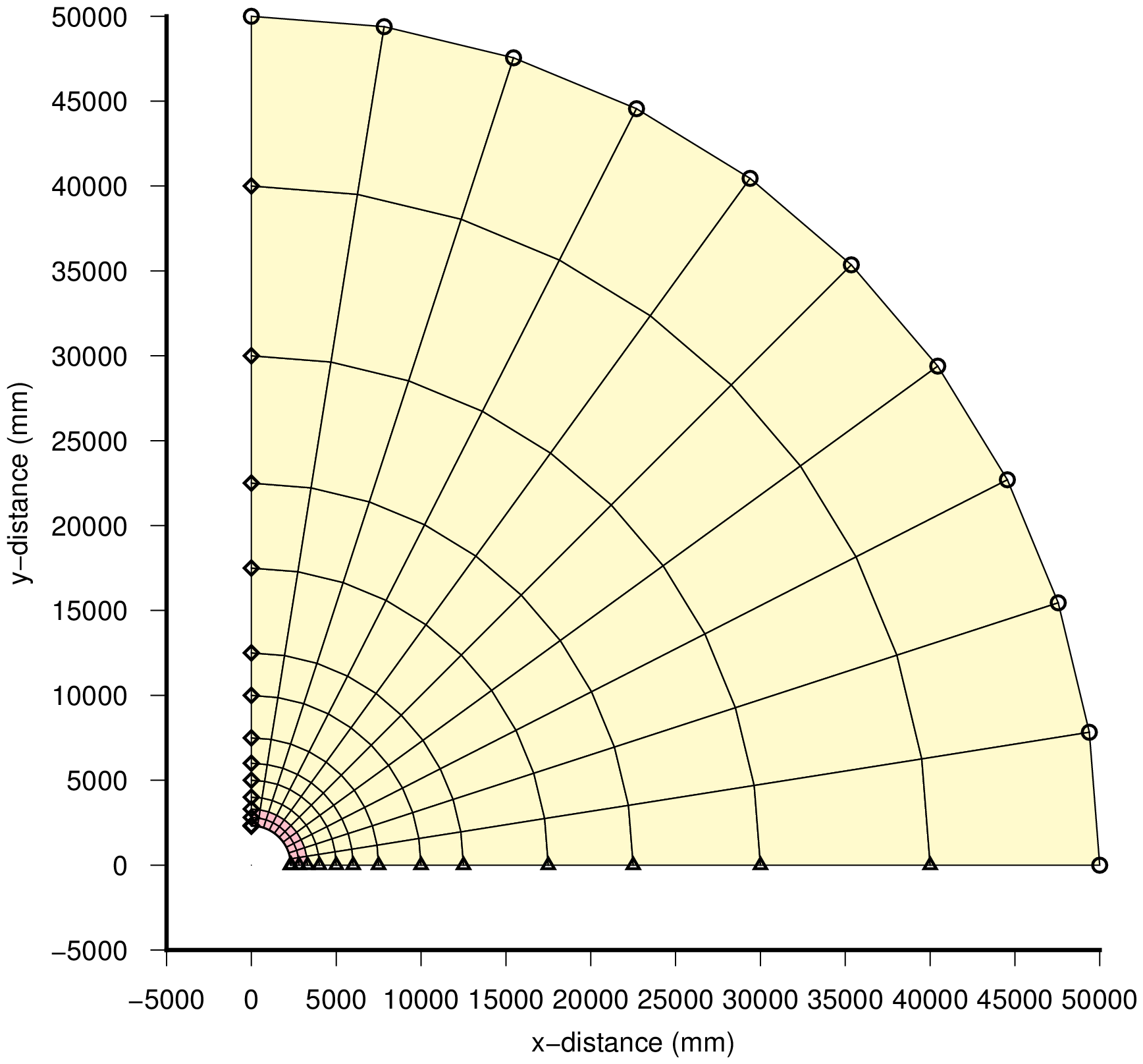 | |
| Mesh | |
|---|---|
 |
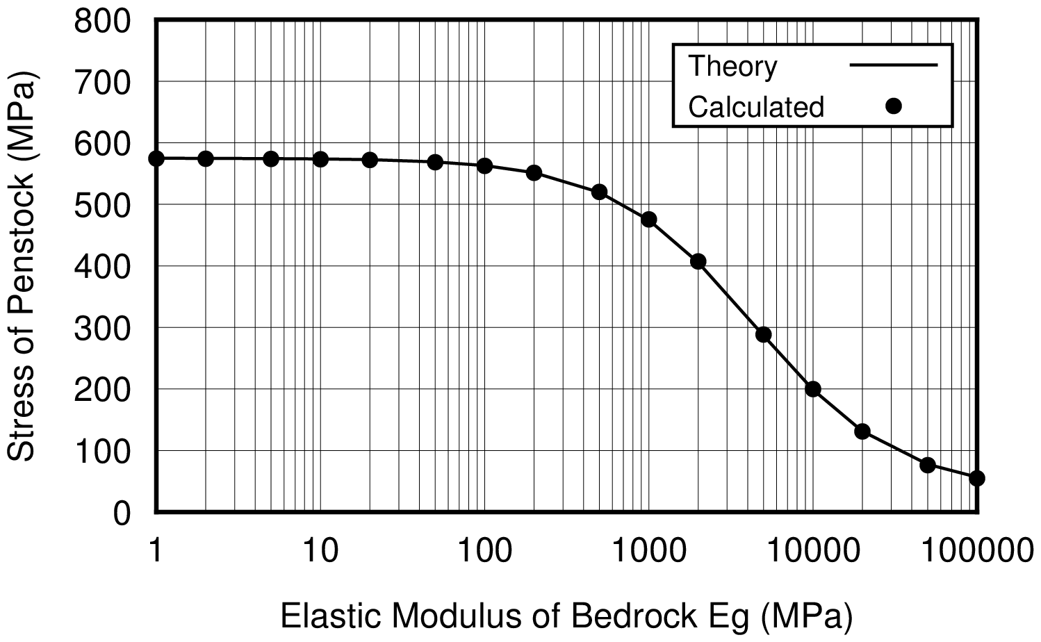 |
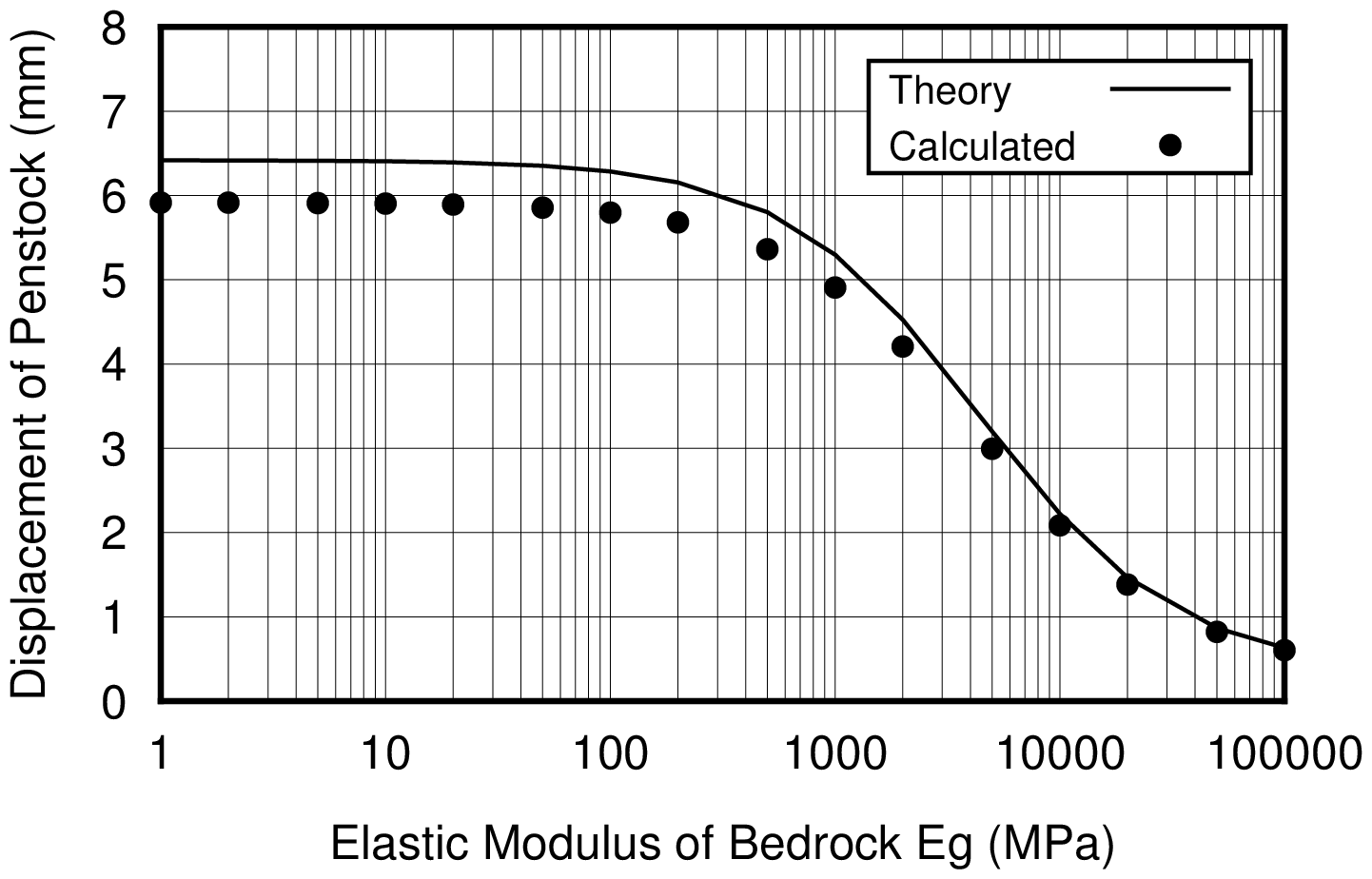
| Displacement of steel pipe | Stress in the steel pipe |
 |
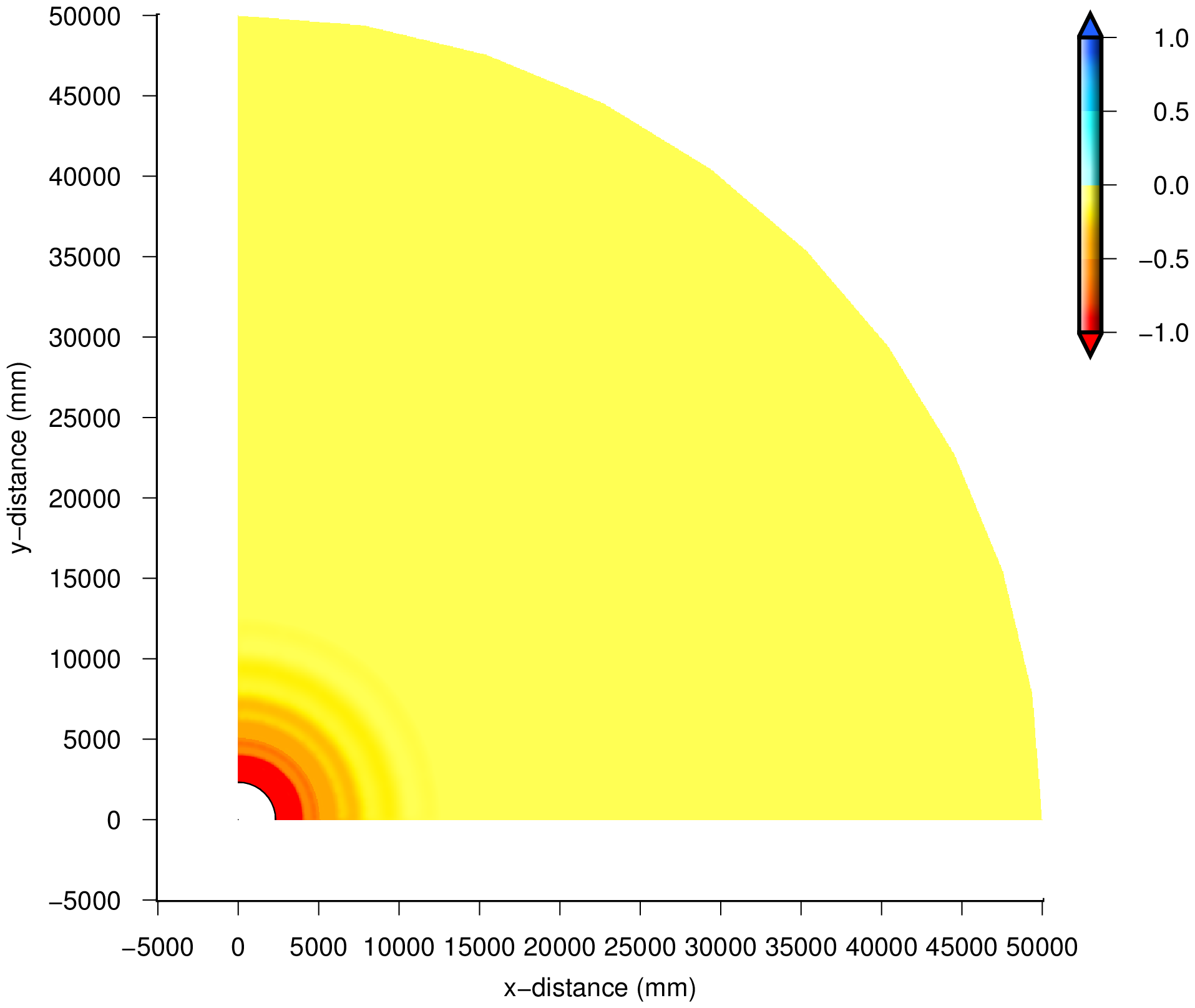 |
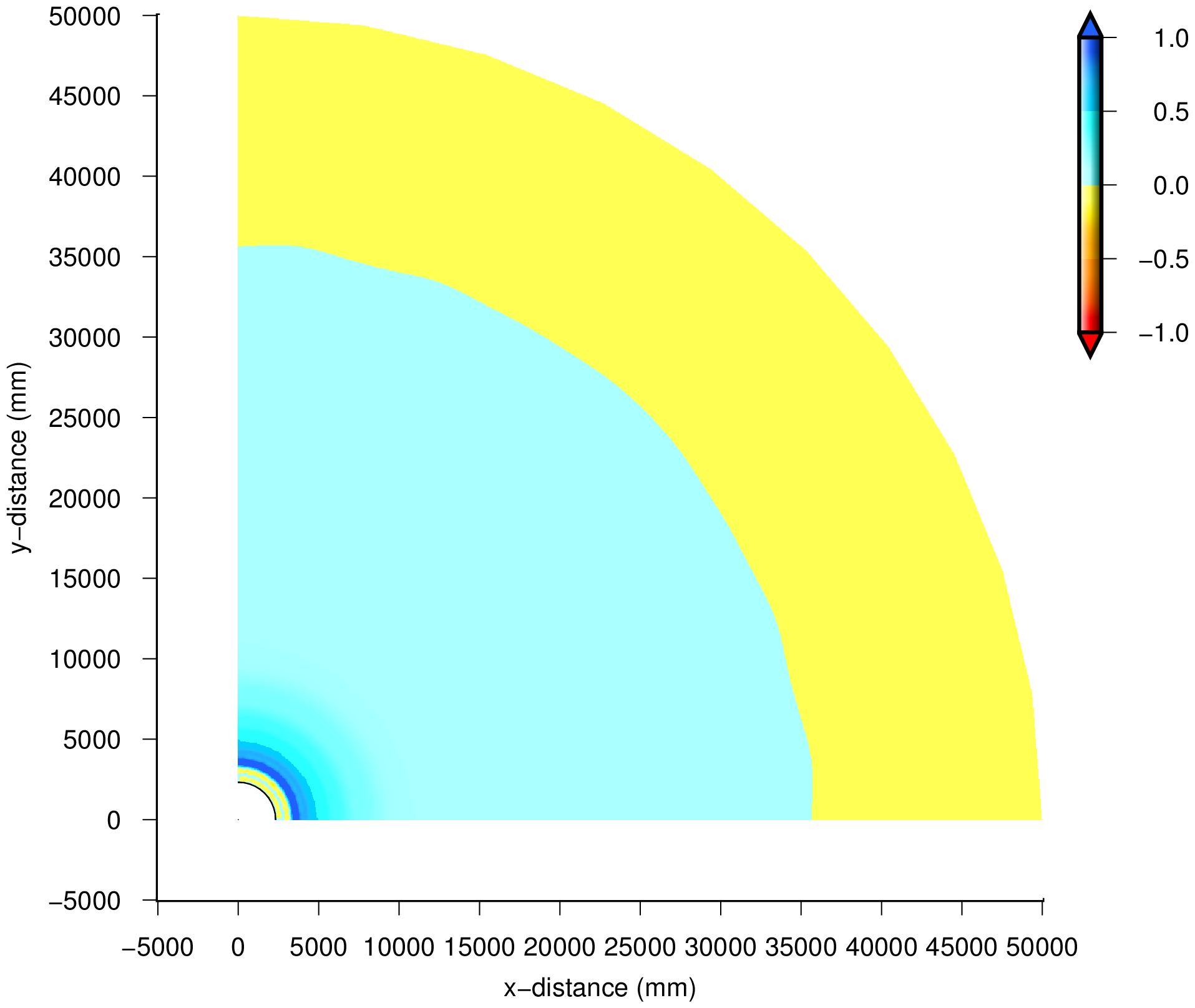
| 1st principal stress distribution | 2nd principal stress distribution |
Programs and sample data
Fortran programs
| Filename | Description |
|---|---|
| f90_fem_plnt.f90 | 2D stress analysis |
| f90_gmt_plnt.f90 | Drawings of stress distributions |
| f90_num_plnt.f90 | Optimization of node numbers (control part) |
| f90_num.f90 | Optimization of node numbers (main part) |
Shell scripts
| Filename | Description |
|---|---|
| a_ps.txt | Shell script for calculation |
| a_gmt_ps.txt | Shell script for drawing |
Input data samples
| Filename | Description |
|---|---|
| inp_4nod_ps.csv | inp_4nod_ps.csv |
| inp_4nod_ps000001.csv | inp_4nod_ps000001.csv |
| inp_4nod_ps000002.csv | inp_4nod_ps000002.csv |
| inp_4nod_ps000005.csv | inp_4nod_ps000005.csv |
| inp_4nod_ps000010.csv | inp_4nod_ps000010.csv |
| inp_4nod_ps000020.csv | inp_4nod_ps000020.csv |
| inp_4nod_ps000050.csv | inp_4nod_ps000050.csv |
| inp_4nod_ps000100.csv | inp_4nod_ps000100.csv |
| inp_4nod_ps000200.csv | inp_4nod_ps000200.csv |
| inp_4nod_ps000500.csv | inp_4nod_ps000500.csv |
| inp_4nod_ps001000.csv | inp_4nod_ps001000.csv |
| inp_4nod_ps002000.csv | inp_4nod_ps002000.csv |
| inp_4nod_ps005000.csv | inp_4nod_ps005000.csv |
| inp_4nod_ps010000.csv | inp_4nod_ps010000.csv |
| inp_4nod_ps020000.csv | inp_4nod_ps020000.csv |
| inp_4nod_ps050000.csv | inp_4nod_ps050000.csv |
| inp_4nod_ps100000.csv | inp_4nod_ps100000.csv |
Expression of the result of 2D stress analysis (f90_gmt_plnt.f90)
Outline
This program can show the FEM mesh and principal stress contour maps by using GMT.
- About programming, it is almost the same as the program for seepage flow analysis.
- In this program, it is possible to specify the elements (materials) which are not used for contour creation.
- Although the pressure head value or total head value which can be found in seepage flow analysis change continuously, the stress which can be found in stress analysis may not change continuously because of differences of characteristics of materials.
- Then, if all stress values are used for contour creation, unforeseen result may be obtained.
- Therefore, the above-mentioned special treatment is made possible.
Following files must be prepared before execution of the program.
| Filename | Description | Remarks |
|---|---|---|
| _col_mesh.txt | Input file for defining mesh color | Filename is fixed |
| _inp_base.txt | Input file for drawing information | Filename is fixed |
| 0_cpt.cpt | Input cpt file for reading by GMT | Filename is fixed |
| fnameW.csv | Output file by FEM analysis | Filename is changeable |
Output file by FEM analysis is a output by the program 'f90_fem_plnt' made by webmaster.
Description of Shell script
Shell script (a_gmt_ps.txt) file which carries out the process is shown below. Some files which are read from Fortran program are made in this batch file.
001   gfortran -o f90_gmt_plnt f90_gmt_plnt.f90
002
003   gmt makecpt -Cno_green -T-1/1/0.1 -I -Z > 1_cpt.cpt
004   awk '{a[NR]=$0}END{for(i=1;i<=NR-1;i++){print a[i]};gsub(/(127.5)/,"255",a[NR]);print a[NR]}' 1_cpt.cpt > 0_cpt.cpt
005
006   # define of drawing data
007   # integer::ind,ibc,ifc,isc
008   # real(4)::baselength,grdspc
009   # real(4)::bav,bfv
010   # real(4)::conint,annint
011   # character::strx*100,stry*100
012   # integer::ncut,numcut(10)
013   cat << EOT > _inp_base.txt
014    0 1 0 1
015    12.0 50
016    5000.0 5000.0
017     0.5 0.5
018    "x-distance (mm)"
019    "y-distance (mm)"
020     1 1
021   EOT
022
023   # define of mesh colour (1:MATEL)
024   cat << EOT > _col_mesh.txt
025    0,0,0
026    255,192,203
027    255,250,205
028   EOT
029
030   ./f90_gmt_plnt out_4nod_ps.csv
031   cp _fig_gmt_mesh.eps fig_gmt_mesh_ps.eps
032   cp _fig_gmt_ps1.eps fig_gmt_ps1_ps.eps
033   cp _fig_gmt_ps2.eps fig_gmt_ps2_ps.eps
034
035   rm _*
001
To compile the program 'f90_gmt_plnt.f90'
003
To make file '1_cpt.cpt' by GMT command 'makecpt.' In this case, 'no_green' is used as the base file, and set range of -1 to 1, set sign as reverse of default.
004
To make file '0_cpt.cpt' using 'awk.' In this treatment, the color 'gray' in last row of file '1_cpt.cpt' is changed to the color 'white.'
013-021
To make the file '_inp_base.txt.' This file defines the parameter for GMT.
| ind | Draw node number and element number in FEM mesh. (0: no, 1: yes) |
| ibc | Draw boundary conditions in FEM mesh. (0: no, 1: yes) |
| ifc | draw load conditions in FEM mesh. (0: no, 1: yes) |
| isc | Draw scale map for contour. (0: no, 1: yes) |
| baselength | Size of drawing in unit of 'cm' |
| grdspc | Mesh interval for 'grd' file |
| bav | Value of 'a' in '-B' option for x and y-axis on GMT |
| bfv | Value of 'f' in '-B' option for x and y-axis on GMT |
| conint | Value of inteval of contour in '-C' option of 'grdcontour' command |
| annint | value of interval of tickmark in '-A' option of 'grdcontour' command |
| strx | Label for x(horizontal)-axis. Double prime (") is required because of character |
| stry | Label for y(vertical)-axis. Double prime (") is required because of character |
| ncut | Number of materials which are not use in contour creation. In this case, it is 'one' for steel penstock. |
| numcut(i) | Material number which is no use in contour creation. In this case, it is 'one' for material number of steel penstock. It is necessary to define 'ncut' and 'numcut' in 1 row. |
024-028
To make the file '_col_mesh.txt.' Mesh colors are defined by this file, 3 figures means 'R G B' in this file. In this example, new file is made using 'cat' hear documents in this script, and since 3 materials are used (parameter MATEL=3), 3 kinds of color is defined.
026
To execute the program 'f90_gmt_plnt.' Functions of this exe file are to make GMT commands, to execute them and to make eps drawings.
Input file 'out_4nod_ps.csv' which storages the result of FEM analysis is read from command line.
Output drawings are shown below.
| Filename | Description | Remarks |
|---|---|---|
| _fig_gmt_mesh.eps | FEM mesh in eps format | filename is fixed |
| _fig_gmt_ps1.eps | 1st principal stress contour in eps format | filename is fixed |
| _fig_gmt_ps2.eps | 2nd principal stress contour in eps format | filename is fixed |
| Symbols for boundary conditions in FEM mesh drawing | |
|---|---|
| Symbol | Description |
| ◇ | Boundary of given displacement in x-direction |
| △ | Boundary of given displacement in y-direction |
| ○ | Boundary of given displacement in both of x and y-directions |
031-033
Since output filename is fixed, it is necessary to change the output filename into another name by a copy command etc after output.
035
To delete work files.