Contents
Special Features of Intake/Outlet in PSPP
General Features
Two different hydraulic functions are required for Intake/Outlet, since the flow direction is reversed in generation and pumping up modes.
Therefore, following issues should especially be considered in hydraulic design of Intake/Outlet in PSPP.
- To prevent occurrence of vortex is necessary. Because of deep available drawdown range and small space under low water level, vortex may occur and entrain the air which gives damage to pump-turbine (cavitations).
- To prevent trash rack from resonance fracture. Because the design velocity of Headrace / Tailrace (about 6.5m/s) are larger than those of conventional hydropower plants generally.
- Study on Outlet velocity to avoid erosion of the opposite bank slope of the reservoir may be necessary according to geological conditions.
Adoptable Measures
Adoptable measures are as follows:
(1) Prevention of vortex
- To control average intake velocity less than 1.0m/s.
- To install anti-vortex girders.
(2) Prevention of resonance fracture of trash rack
- To control maximum Intake/Outlet velocity less than about 2.5m/s.
- To improve rigidity of trash rack.
(3) Prevention of erosion of opposite bank slope
- To reduce Outlet velocity and reduce the velocity of opposite side bank slope less than about 0.5m/s.
- To make protection of opposite bank slope.
Design of Lateral Type Intake/Outlet
Designs are conducted as follows based on hydraulic model tests by Central Research Institute of Electric Power Industry in Japan and design and construction experiences of PSPP in Japan.
Basic Figure
Fan shape with partition wall is the basic design of Lateral Type Intake/Outlet, to control average intake velocity and maximum outlet velocity.
To prevent separation and reverse of water flow, each element of the structure is designed as follows.
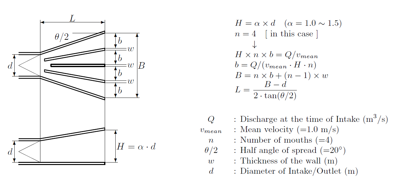
- Height of mouth at trash rack is generally 1.0 to 1.5 times as that of Headrace/Tailrace tunnel. In this case, the height is designed as well as that of Headrace/Tailrace to reduce construction costs of whole civil works in the reservoirs, especially the cofferdams.
- Gradual-expansion section is generally divided into 2 to 4 by partition walls. In this case, all lateral type Intake/Outlet structures have 4 sections, according to the study as shown in 2.3.
- Horizontal angle of one gradual-expansion section is generally less than 10 degree.
Figure Designed for Average Intake Velocity
Structures are designed to meet requirement of average Intake velocity as follows.
- Height of mouth at trash rack (H) : $\alpha$ times as that of Headrace/Tailrace (d), where $\alpha$=1.0$\sim$1.5
- Number of mouths (n) : 4 according to experiences.
- Width of one mouth at trash rack (b): b is calculated as division of Design discharge (Q) by average Intake velocity (=1.0m/s), height of mouth (H) and number of sections (n).
- Length of gradual-expansion section (L) : set by horizontal angle of 0$\sim$10 degree per mouth.
 |
| The shape based on Intake velocity |
|---|
Figure Designed for Maximum Outlet Velocity
Control of maximum Outlet velocity is necessary for preventing trash rack from resonance fracture and erosion of opposite bank slope of reservoir.
Structure is designed to meet requirement of maximum Outlet velocity as follows.
- To calculation maximum Outlet velocity based on the figure designed for average Intake velocity.
- If maximum Outlet velocity exceeds required velocity, number of mouth (n) and length of gradual-expansion section (L) are changed. In this case, all lateral type Intake/Outlet structures meet the requirement, therefore, no more changes are needed.
- The graph shown below which derived from a lot of experiment studies done by Central Research Institute of Electric Power Industry in Japan, is used for calculation of maximum Outlet velocity.
| $v_{max}$ | : Maximum Outlet velocity at trash rack |
| $v_0$ | : Mean velocity of Headrace or Tailrace tunnel |
| $L$ | : Length of gradual-expansion section |
| $d$ | : Diameter of Headrace or Tailrace tunnel |
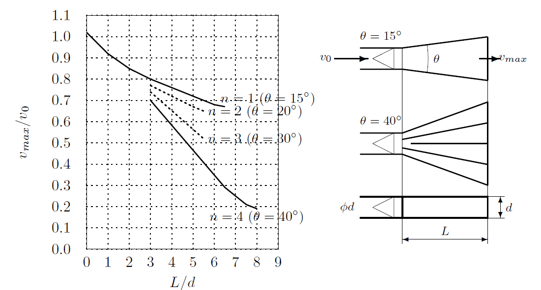 |
Relationship between the length of gradual-expansion section
and maximum Outlet velocity at trash rack (by CRIEPI inJapan) |
|---|
Control of Velocity at Opposite Bank Slope of Reservoir
Velocity at opposite bank slope of the reservoir should be limited to required level that has no possibility of erosion and slope collapse.
The length of gradual-expansion section is needed to be extended to reduce maximum Outlet velocity.
To control velocity at the opposite bank slope of reservoir, length of gradual-expansion section is set based on the following graph which shows relation between distance to opposite side and its velocity.
This graph is cited from the result of study on three-dimensional jets. (Turbulent Jets : N.Rajaratnam)
| $v$ | : Velocity at opposite bank (m/s) |
| $v_{max}$ | : Maximum Outlet velocity at trash rack (m/s) |
| $x$ | : Distance to opposite bank (m) |
| $A$ | : Square measure of one separated area (m$^2$) |
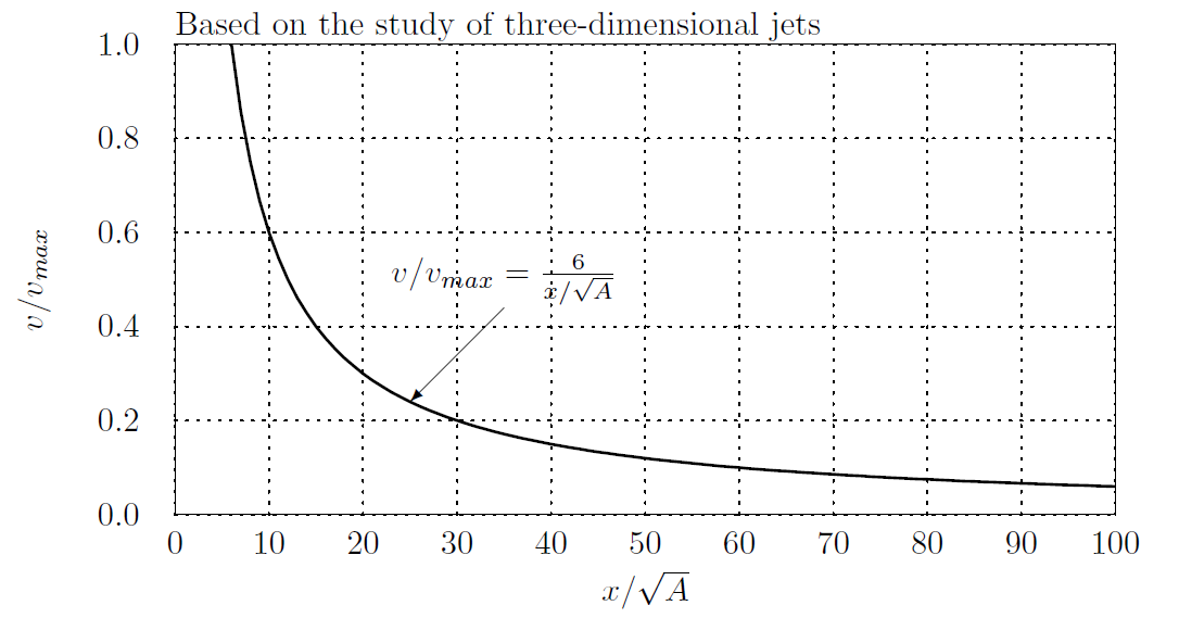 |
| Relationship between the distance to opposite bank and its velocity |
|---|
(Reference) Allowable Mean Velocity for Non-adhesive Grain
The allowable mean velocity of the 1mm's non-adhesive grain is considered to be 0.55m/s.
(Source: Hideo KIKKAWA, KASEN-KOUGAKU [River engineering], Asakura Publishing Co., Ltd. Japan)
| Allowable velocity of non-adhesive grain |
|---|
| d (mm) | v (m/s) | Remarks |
|---|
| 0.005 | 0.15 | $d$ : Particle size
$v$ : Mean allowable velocity |
| 0.05 | 0.20 |
| 0.25 | 0.30 |
| 1.00 | 0.55 |
| 2.50 | 0.65 |
| 5.00 | 0.80 |
| 10.00 | 1.00 |
| 15.00 | 1.20 |
| 25.00 | 1.50 |
| 40.00 | 1.80 |
| 75.00 | 2.40 |
| 100.0 | 2.70 |
Prevention of Occurrence of Vortex
To prevent occurrence of vortex, the average Intake velocity is limited to less than 1.0m/s, and anti-vortex girders are installed.
It is applied for the reservoir which has deep available drawdown range and little space between LWL and top elevation of Intake/Outlet.
Anti-vortex girder works for preventing vortex occurrence focusing on the following features of vortex.
Vortex goes around in a specific area and doesn't stay in a same place, and it hardly occurs while the center of vortex flow is obstructed.
Therefore, girders are set in appropriate spans in the vortex moving area, where the center of flow strikes.
 |
| Design of anti-vortex girder (by CRIEPI in Japan) |
|---|
Prevention of Resonance Fracture for Trash Rack
If the velocity is too high, Karman vortex occurs and vibrates the trash rack steel bar at the right angle to the water flow.
To prevent trash rack from resonance fracture, the characteristic frequency of trash rack steel bar should be more then 2.5 times of that of Karman vortex.
(Technical Standards for Gates and Penstocks: Hydraulic Gate and Penstock Association, Japan)
The following measures are taken.
- To control maximum Intake/Outlet velocity.
- To improve the rigidity of trash rack steel bar. This means to increase the thickness of trash rack steel bar, or to decrease the supporting interval of trash rack steel bar.
\begin{equation*}
\frac{f_n}{f}\geqq 2.5
\end{equation*}
\begin{equation*}
f=S_t\cdot\cfrac{V}{t} \qquad
f_n=\frac{\alpha}{2\pi}\cdot\sqrt{\frac{E\cdot I\cdot g}{W\cdot L^3}} \qquad
W=Q\cdot\left(\gamma+\frac{b}{t}\cdot\gamma_w\right)
\end{equation*}
| $f_n$ | : Natural frequency of trash rack steel bar (Hz) |
| $f$ | : Frequency of vibratory force by Karman's vortex (Hz) |
| $V$ | : Flow velocity at trash rack (mm/s) |
| $t$ | : Thickness of steel bar (mm) |
| $S_t$ | : Strouhal number (=0.2) |
| $\alpha$ | : Coefficient of supporting condition |
| | ($\alpha=\pi^2$ for simple support, $\alpha=4\pi^2/\sqrt{3}$ for fixed support) |
| $E$ | : Elastic modulus of steel bar (=206,000 N/mm$^2$) |
| $I$ | : Second moment of steel bar area (mm$^4$) |
| $g$ | : Gravitational acceleration (=9,800 mm/s$^2$) |
| $L$ | : Supporting interval of steel bars (mm) |
| $W$ | : Weight of steel bar and water around it (N) |
| $Q$ | : Volume of steel bar (mm$^3$) |
| | ($Q=t\cdot B\cdot L$) |
| $\gamma$ | : Unit weight of steel bar (=76.93*10$^{-6}$ N/mm$^3$) |
| $\gamma_w$ | : Unit weight of water (=9.8*10$^{-6}$ N/mm$^3$) |
| $B$ | : Width of steel bar (mm) |
| $b$ | : Effective interval of steel bars (mm) |
| | ($b=c - t$) |
| $c$ | : Interval of steel bars (center to center) |
| (Reference) Example of calculation of fn/f |
|---|
| $L$ (mm) | 600 | 500 | 400 |
| $f_n$ (Hz) | 71.8 | 103.4 | 161,6 |
| $t$=16mm, $B$=100mm, $c$=150mm |
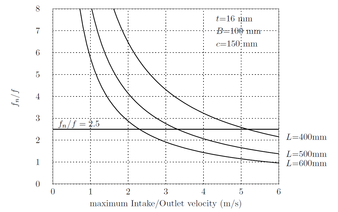 |
| Relationship between maximum Intake/Outlet velocity and $f_n/f$ |
|---|
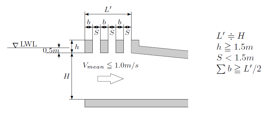
Placement and Figure of Partition Wall
Standard of placement and figure of the partition wall is suggested by the study of Central Research Institute of Electric Power Industry in Japan as follows.
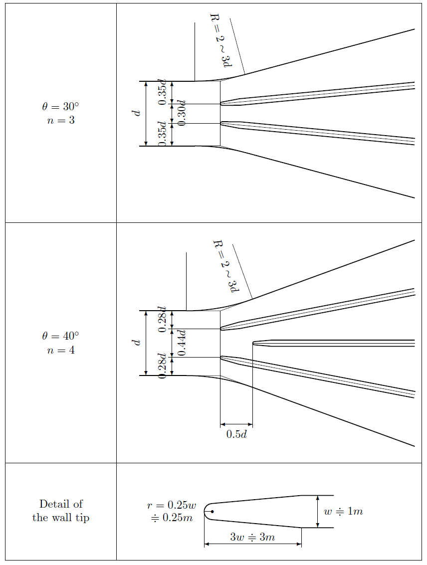 |
| Detailed shape of the partition wall (by CRIEPI in Japan) |
|---|
Design of Morning Glory Type Intake
General Features
There is another type of intake of PSPP, Morning Glory Type. The type has the following advantages and disadvantages compared with lateral type.
- The storage water can be used effectively, since the intake is located on the bottom of the reservoir.
- Outlet velocity is efficiently reduced, since the flow spreads to the all direction laterally.
- The distance between intake and headrace is longer than that of lateral type, since the morning glory type is located around the center of the reservoir.
- Generally, reservoir should be totally empty while the waterway is being maintained, since any gates cannot be installed in the intake.
According to the characteristics above, the morning glory type is generally applied especially to upper reservoirs which has small sedimentation inflow and can be made totally empty, and is artificially excavated pond type.
Basic Design
There are not enough examples to make a design standard of the morning glory type intake.
Therefore, basic design are referred to the intake which has similar conditions.
Sample requirements are shown as follows:
| Features | Requirements |
|---|
| Degree of the Screen | 1:0.3 |
| Velocity at the Screen | Less than 0.5m/s |
| Velocity at the beginning of Bellmouth | Less than 0.7m/s |
| Shape of the Bellmouth | Curve : $(x/a)^2+(y/b)^2=1 , \quad b/a\doteqdot 3.6$
Where,
$a$ : difference between the radiuses of the
beginning and the end of the bellmouth
$b$ : length of the bellmouth |
| Width of screen peer | 1.0m |
| Thickness of the top part | 1.0m |
| Elevation of the Inflow Top | L.W.L$-$0.5m |
| Length of Vertical Waterway | More than 36.0m
(beginning of the bellmouth - waterway VIP) |