Outline of a program 'f90_fem_truss.f90'
- This is a program for Grid Gurder Analysis. Elastic and small displacement problems can be treated. This progmam has been made from 'f90_fem_frame.f90.'
- Beam element with 2 nodes is used. 1 node has 3 degrees of freedom which are torsional rotation, bending rotation and deflection.
- Simultaneous linear equations are solved using Cholesky method for banded matrix.
- Input/Output file name can be defined arbitrarily with the format of 'csv' and those are inputted from command line of a terminal.
- Used language for program is 'Fortran 90' and used compiler is 'GNU gfortran.'
| Workable condition | |
|---|---|
| Item | Description |
| Element | Beam element which can treat St. Venant Torsion. |
| Load | Specify the loaded nodes and load values |
| Displacement | Specify the nodes and displacements at the nodes. Any values can be applied including zero |
 |
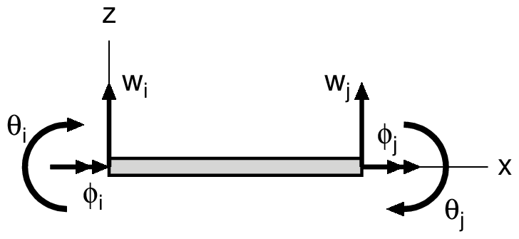 |
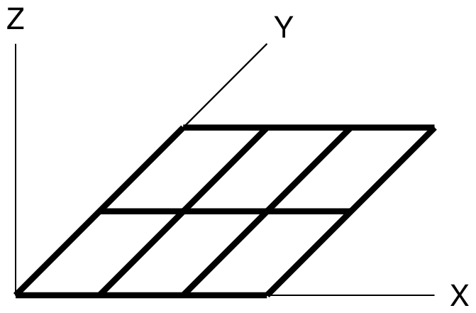
| Global Coordinate System | Local Coordinate Syatem |
|---|
The Stiffness matrix of an element is shown below:
\begin{equation*}
\begin{Bmatrix} T_i \\ M_i \\ Q_i \\ T_j \\ M_j \\ Q_j \end{Bmatrix}
=\begin{bmatrix}
GJ/L & 0 & 0 & -GJ/L & 0 & 0 \\
0 & 4 EI/L & -6 EI/L^2 & 0 & 2 EI/L & 6 EI/L^2 \\
0 & -6 EI/L^2 & 12 EI/L^3 & 0 & -6 EI/L^2 & -12 EI/L^3 \\
-GJ/L & 0 & 0 & GJ/L & 0 & 0 \\
0 & 2 EI/L & -6 EI/L^2 & 0 & 4 EI/L & 6 EI/L^2 \\
0 & 6 EI/L^2 & -12 EI/L^3 & 0 & 6 EI/L^2 & 12 EI/L^3
\end{bmatrix}
\begin{Bmatrix} \phi_i \\ \theta_i \\ w_i \\ \phi_j \\ \theta_j \\ w_j \end{Bmatrix}
\end{equation*}
| $GJ$ | Torsional rigidity | $T$ | Torsional moment | $\phi$ | Rotation around x-axis | ||
| $EI$ | Bending rigidity | $M$ | Bending moment | $\theta$ | Rotation around y-axis | ||
| $L$ | Length of element | $Q$ | Shearing force | $w$ | Displacement in z-direction |
Since the coordinate transformation is carried out on the x-y plane only, the transfoemation matrix is the same type as it for 2D frame analysis.
Format of input data file ('csv' format)
Comment                         # Comments
NODT,NELT,MATEL,KOX,KOY,KOZ,NF  # Basic values for analysis
Em,AA,AI,AJ                     # material properties
    ....(1 to MATEL)....        #
node-1,node-2,matno,qw          # Element connectivity, material set number, uniformly distributed load per unit length
    ....(1 to NELT)....         #
x,y                             # Node coordinates, temperature change of node
    ....(1 to NODT)....         #
nokx,rdisx                      # Restricted node number and rotation around x-axis (member axis)
    ....(1 to KOX)....          # (Omit data input if KOX=0)
noky,rdisy                      # Restricted node number and rotation around y-axis
    ....(1 to KOY)....          # (Omit data input if KOY=0)
nokz,rdisz                      # Restricted node number and displacement in z-direction
    ....(1 to KOZ)....          # (Omit data input if KOZ=0)
node,fx,fy,fz                   # loaded node number, Load value in x, y & z-direction
    ....(1 to NF)....           # (Omit data input if NF=0)
| NODT | : Number of nodes | Em | : Elastic modulus of element |
| NELT | : Number of elements | AA | : Section area of element |
| MATEL | : Number of material sets | AI | : Moment of Inertia of element |
| KOX | : Number of restricted nodes in x-direction | AJ | : Tosion constant |
| KOY | : Number of restricted nodes in y-direction | matno | : Material set number |
| KOZ | : Number of restricted nodes in rotation | qw | : uniformly distributed load per unit length |
| NF | : Number of loaded nodes |
Notice
- The structure shall be defined on the x-y plane in the global coordinate system.
- x-direction in the local coordinate system means the member axis.
- The displacement in local x-direction means the rotation around the x-axis, which is same as torsional rotation.
- The displacement in local y-direction means the rotation around the y-axis, which is same as bending rotation.
- The displacement in local z-direction means the deflection of the beam.
- Restricted node means the node which has known (given) displacement. As a known (given) value of nodal displacement, any value can be given including zero for a restricted node.
- Since stress resultants of element are defined as equivalent nodal forces in local coordinate system, it is necessary to note that signs are different from it on general structural mechanics. Positive directions are always right-direction, upward-direction for each node in local coordinate system.
Format of output file ('csv' format)
Comment
NODT,NELT,MATEL,KOX,KOY,KOZ,NF
(Each value for above item)
*node characteristics
node,x,y,fx,fy,fz,fix-x,fix-y,fix-z,rdis-x,rdis-y,rdis-z
    node     : Node number
    x,y      : x & y-coordinates
    fx,fy    : Nodal forces in x & y direction and Moment of node
    fix-x    : x-direction restricted condition (1: restricted, 0: not restricted)
    fix-y    : y-direction restricted condition (1: restricted, 0: not restricted)
    fix-z    : z-direction restricted condition (1: restricted, 0: not restricted)
    rdis-x   : Displacements in x-direction
    rdis-y   : Displacements in y-direction
    rdis-z   : Displacements in z-direction
    deltaT   : temperature change of node
  .....(1 to NODT).....
*element characteristics
element,node-1,node-2,E,A,I,J,qw,matno
    element       : Element number
    node-1,node-2 : Element-nodes relationship
    E             : Elastic modulus of element
    A             : Section area
    I             : Moment of Inertia
    J             : Torsion constant
    qw            : Uniformly distributed load per unit length
    matno         : Material set number
  .....(1 to NELT).....
*displacements and forces
node,coord-x,coord-y,dis-x,dis-y,dis-z,reac-x,reac-y,reac-z,ftvec-x,ftvec-y,ftvec-z
    node                    : Node number
    x-cood,y-cood           : Coordinates in x & y-directions
    dis-x,dis-y,dis-z       : Nodal displacements in x, y & z-directions
    reac-x,reac-y,reac-z    : Internal forces in x, y & z-directions
    ftvec-x,ftvec-y,ftvec-z : External forces in x, y & z-directions
  .....(1 to NODT).....
*stress resultants
element,Ti,Mi,Qi,Tj,Mj,Qj
    element : Element number
    Ti,Tj   : Torsional moments at node 'i' and 'j'
    Mi,Mj   : Bending moments at node 'i' and 'j'
    Qi,Qj   : Shear forces at node 'i' and 'j'
  .....(1 to NELT).....
NODT=(Number of node), nt=(nt), mm=(mm), ib=(ib)
Calculation time=(calculation time)
Date_time=(date of execution)
    nt : Total degrees of freedom of FE equation
    mm : Dimension of reduced FE equation
    ib : band width of reduced FE equation
Programs and sample data
| Filename | Description |
|---|---|
| a_fem.txt | Shell script for execution |
| a_gmt_model.txt | GMT command for model drawings |
| f90_fem_grid.f90 | Grid Girder Analysis |
| f90_calj.f90 | Calculation of Torsion constant |
| inp_canti_1.txt | Input data sample (1) |
| inp_canti_2.txt | Input data sample (2) |
The torsion constant for a rectanglar solid section 'J' can be obtained using following equation and a program 'f90_calj.f90.'
\begin{equation*}
J=\cfrac{1}{3} b a^3 \left\{1-\cfrac{192}{\pi^5}\cfrac{a}{b}\sum_{n=1}^\infty\cfrac{1}{(2n-1)^5}\tanh\cfrac{(2n-1)\pi b}{2 a}\right\}
\qquad (b \geqq a)
\end{equation*}