Outline of a program 'f90_fem_gfrmwp.f90'
- On the program 'f90_fem_gfrm.f90,' it is assumed that the directions of loads don't change before and after deformation. However, when water pressure is considered as a load to a structure, it always acts in perpendicular direction on the surface of a structure. Then, the program was amended so that the behavior of a structure under the uniform distributed water pressure could be simulated using this program 'f90_fem_gfrmwp.f90.'
| Workable condition | |
|---|---|
| Item | Description |
| Element | 2D beam element. Geometrically Nonlinear behavior of a frame under the uniform water pressure can be simulated. |
| Load | Specify the loaded nodes and load values. It is assumed that the load directions are perpendicular to the beam element in the local coordinate system everytime. |
| Displacement | Specify the nodes which are completely fixed. Only zero displacement can be considered. |
Input data from command line
./f90_fem_gfrmwp fnameR fnameW nlmax itmax coefA
| f90_fem_gfrmwp | Compiled program |
| fnameR | Input filename |
| fnameW | Output filename |
| nlmax | Limit of Loading steps |
| itmax | Limit of Iteration steps |
| coefA | Scaling parameter for Incremental Arc-Lemgth method |
Format of input data file ('csv' format)
Comment                         # Comments
NODT,NELT,MATEL,KOX,KOY,KOZ,NFE # Basic values for analysis
Em,AA,AI                        # material properties
    ....(1 to MATEL)....        #
node-1,node-2,matno             # Element connectivity, material set number
    ....(1 to NELT)....         #
x,y                             # Node coordinates
    ....(1 to NODT)....         #
nokx                            # Fixed node number in x-direction
    ....(1 to KOX)....          # (Omit data input if KOX=0)
noky                            # Fixed node number in y-direction
    ....(1 to KOY)....          # (Omit data input if KOY=0)
nokz                            # Fixed node number in rotation
    ....(1 to KOZ)....          # (Omit data input if KOZ=0)
ne,fx1,fy1,fz1,fx2,fy2,fz2      # External nodal forces in local coordinate
    ....(1 to NFE)....          # (Omit data input if NF=0)
Dpress                          # Water pressure increment
| NODT | : Number of nodes | Em | : Elastic modulus of element |
| NELT | : Number of elements | AA | : Section area of element |
| MATEL | : Number of material sets | AI | : Moment of inertia of element |
| KOX | : Number of fixed nodes in x-direction | matno | : Material set number |
| KOY | : Number of fixed nodes in y-direction | ||
| KOZ | : Number of fixed nodes in rotation | ||
| NFE | : Number of loaded elements (not nodes) | ||
Notice
- Fixed node means the node which is restricted completely.
- Since stress resultants of element are defined as equivalent nodal forces in local coordinate system, it is necessary to note that signs are different from it on general structural mechanics. Positive directions are always right-direction, upward-direction and counterclockwise direction for each node in local coordinate system.
Format of output file ('csv' format)
Comment
NODT,NELT,MATEL,KOX,KOY,KOZ,NFE,nlmax,itmax,Dpress
(Each value for above item)
*node characteristics
node,x,y,dfx,dfy,dfz,fix-x,fix-y,fix-z
    node     : Node number
    x,y      : x & y-coordinates
    dfx,dfy,dfz : Nodal forces in x & y direction and Moment of node
    fix-x    : x-direction restricted condition (1: restricted, 0: not restricted)
    fix-y    : y-direction restricted condition (1: restricted, 0: not restricted)
    fix-z    : Restricted condition for rotation (1: restricted, 0: not restricted)
  .....(1 to NODT).....
*element characteristics
element,node-1,node-2,E,A,I,matno
    element       : Element number
    node-1,node-2 : Element-nodes relationship
    E             : Elastic modulus of element
    A             : Section area of element
    I             : Moment of inertia of element
    matno         : Material set number
  .....(1 to NELT).....
*** New load step ***
nload,iteration,Tpress,lam,deltaS,coefA
(Each value for above item, Tpress is total water pressure)
*displacements and forces
node,coord-x,coord-y,dist-x,dist-y,dist-z,ff-x,ff-y,ff-z,ftvec-x,ftvec-y,ftvec-z
    node                    : Node number
    coord-x,coord-y         : Coordinates in x & y-directions
    dist-x,dist-y,dist-z    : Nodal displacements in x & y & rotation directions
    ff-x,ff-y,ff-z          : External loads in x & y & rotation directions
    ftvec-x,ftvec-y,ftvec-z : Unbalanced forces in x & y & rotation directions
  .....(1 to NODT).....
*stress resultants
element,Ni,Si,Mi,Nj,Sj,Mj
    element : Element number
    Ni,Nj   : Axial forces at node 'i' and 'j'
    Si,Sj   : Shear forces at node 'i' and 'j'
    Mi,Mj   : Moments at node 'i' and 'j'
  .....(1 to NELT).....
*** New load step ***
.....
=== (1 to nlmax) ===
.....
NODT=(Number of nodes) nt=(nt) mm=(mm)
Calculation time=(calculation time)
Date_time=(date of execution)
    nt : Total degrees of freedom of FE equation
    mm : Dimension of reduced FE equation
Sample drawings
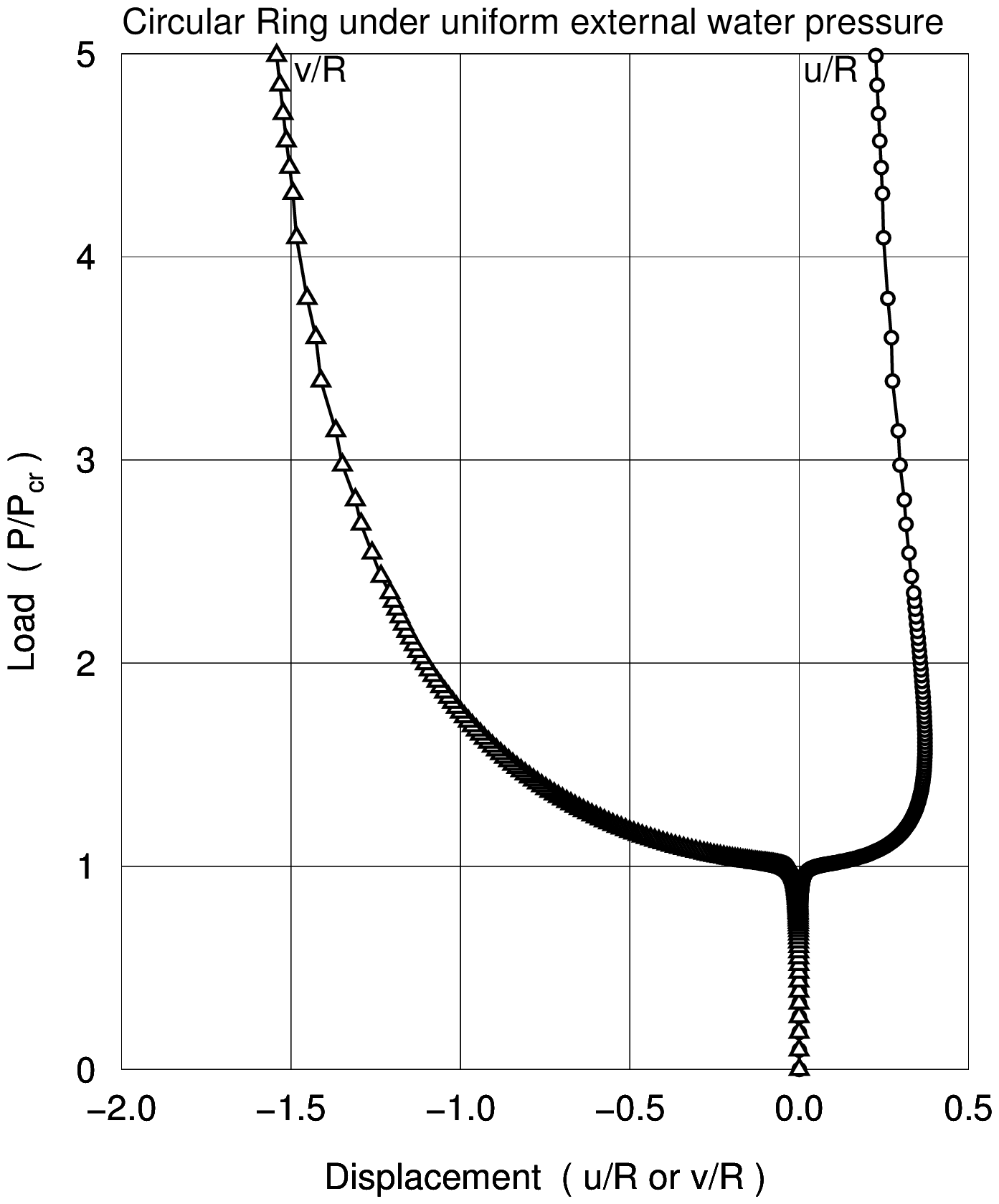
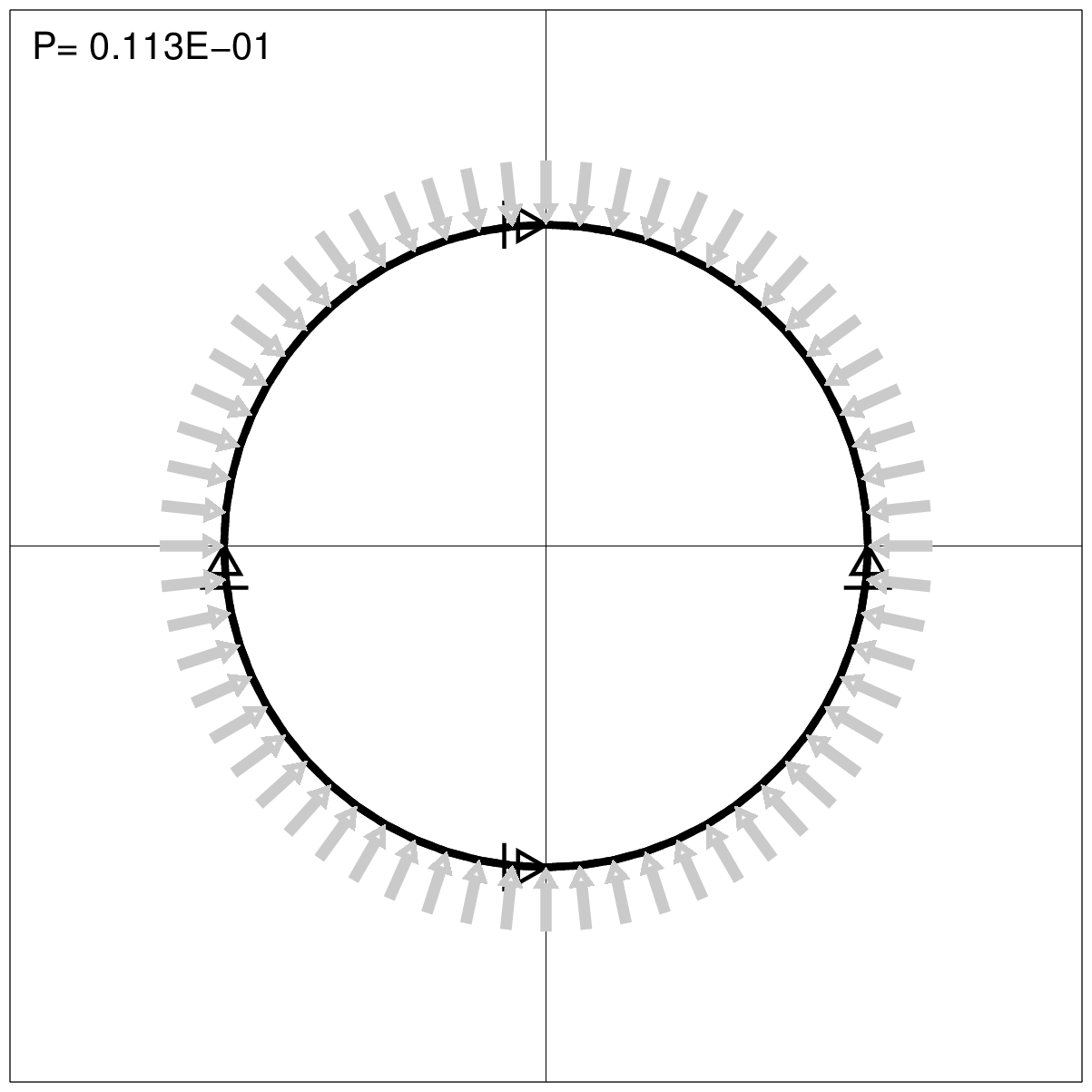
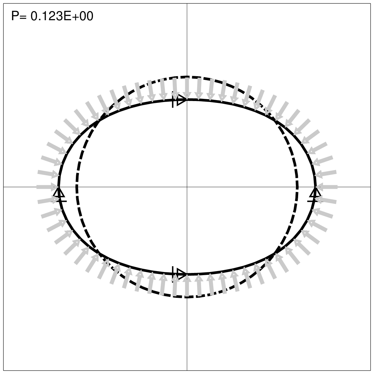
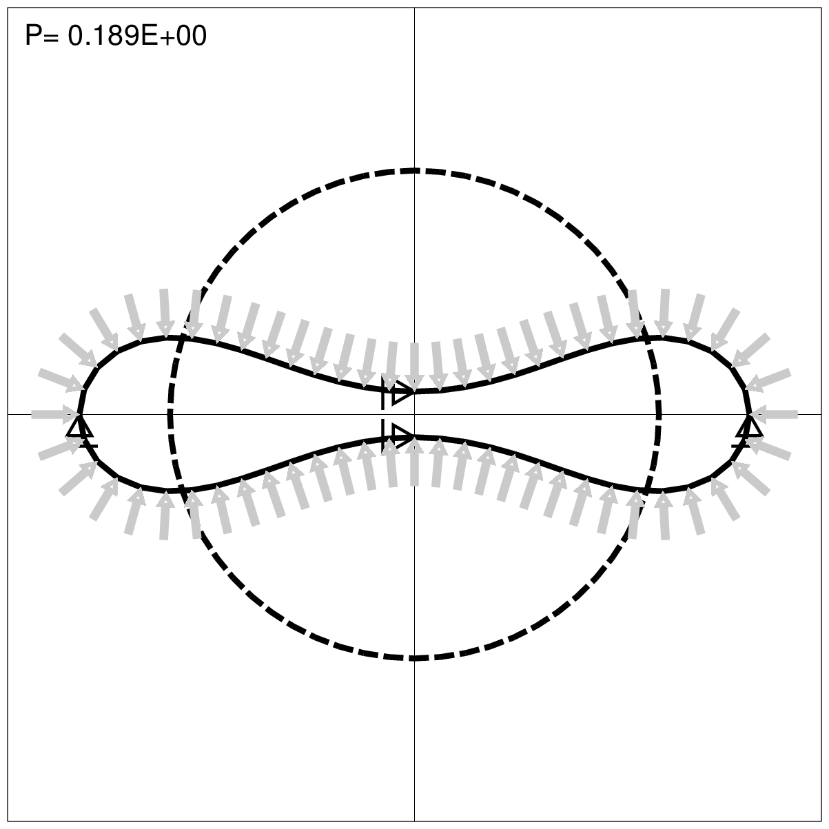
Ring under the external water pressure
| R=1,500 mm | r = 1500 + 1.5 x cos(2$\theta$) |
| E=200,000 N/mm$^2$ | x = r x cos$\theta$ |
| A=20 mm$^2$ | y = r x sin$\theta$ |
| I=666.6 mm$^4$ | |
| Initial deflection 1.5 mm | |
| Buckling pressure Pcr=3EI / R$^3$ =0.1185 N/mm$^2$ |
 | |
 |
 |
 |
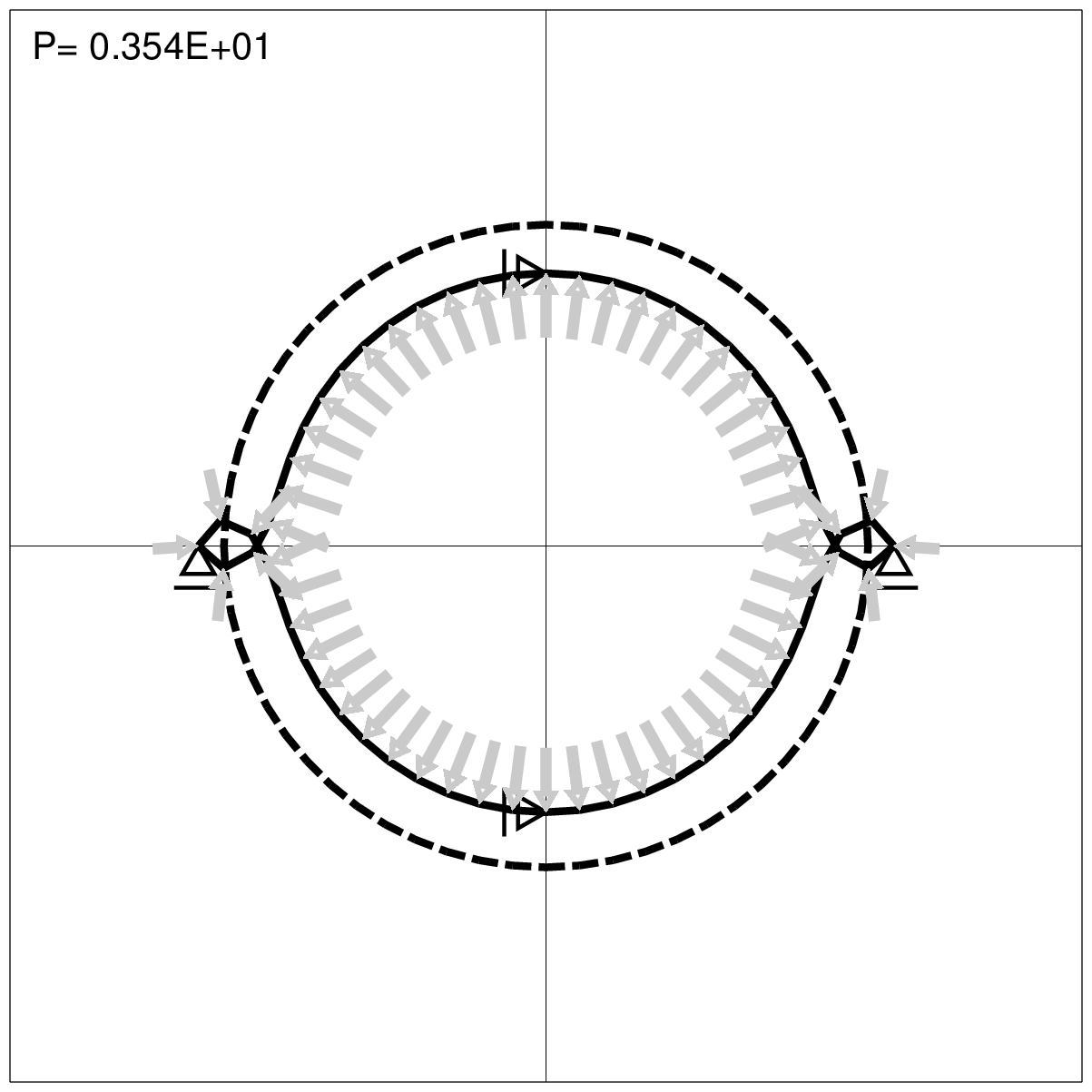 |
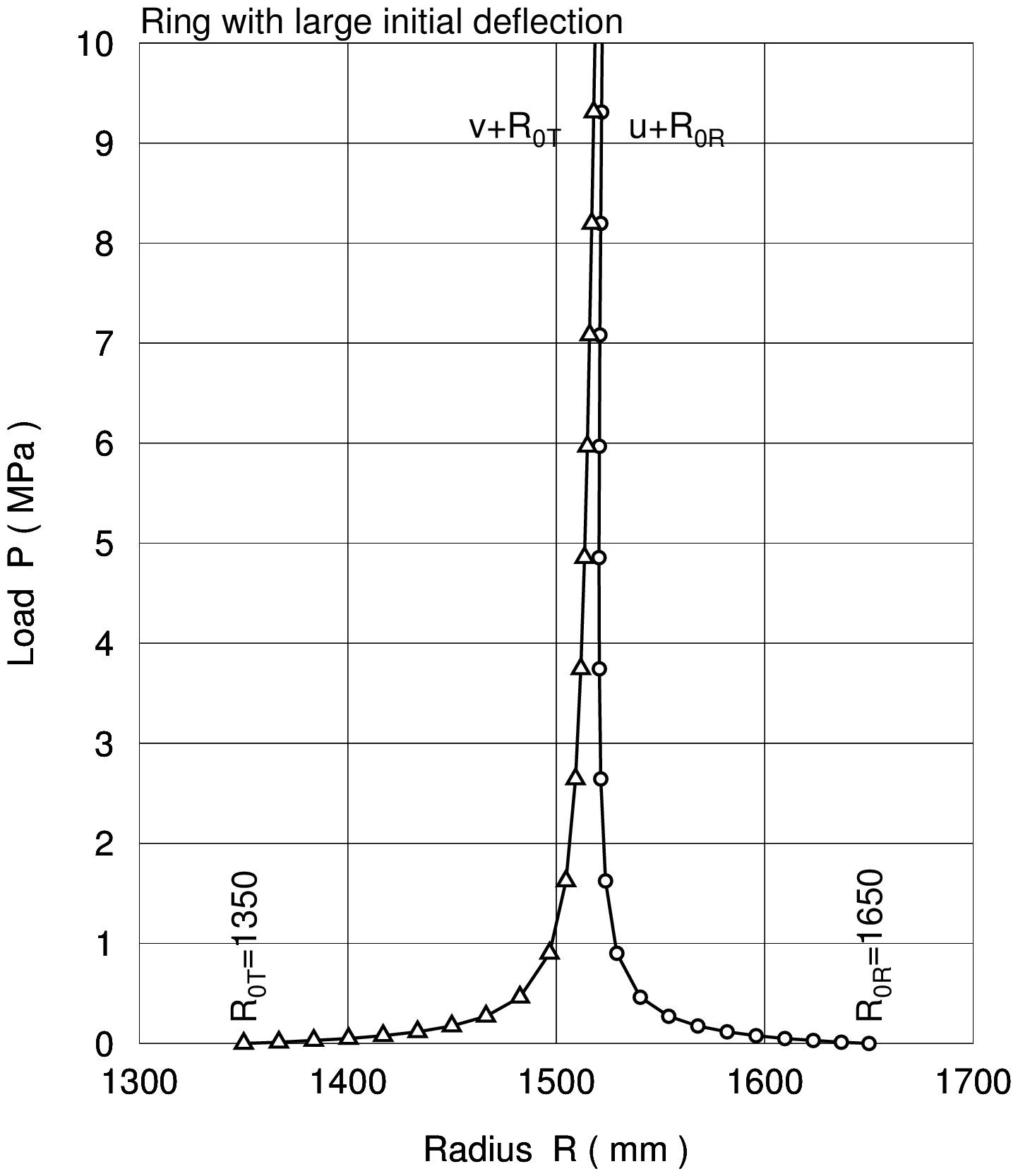
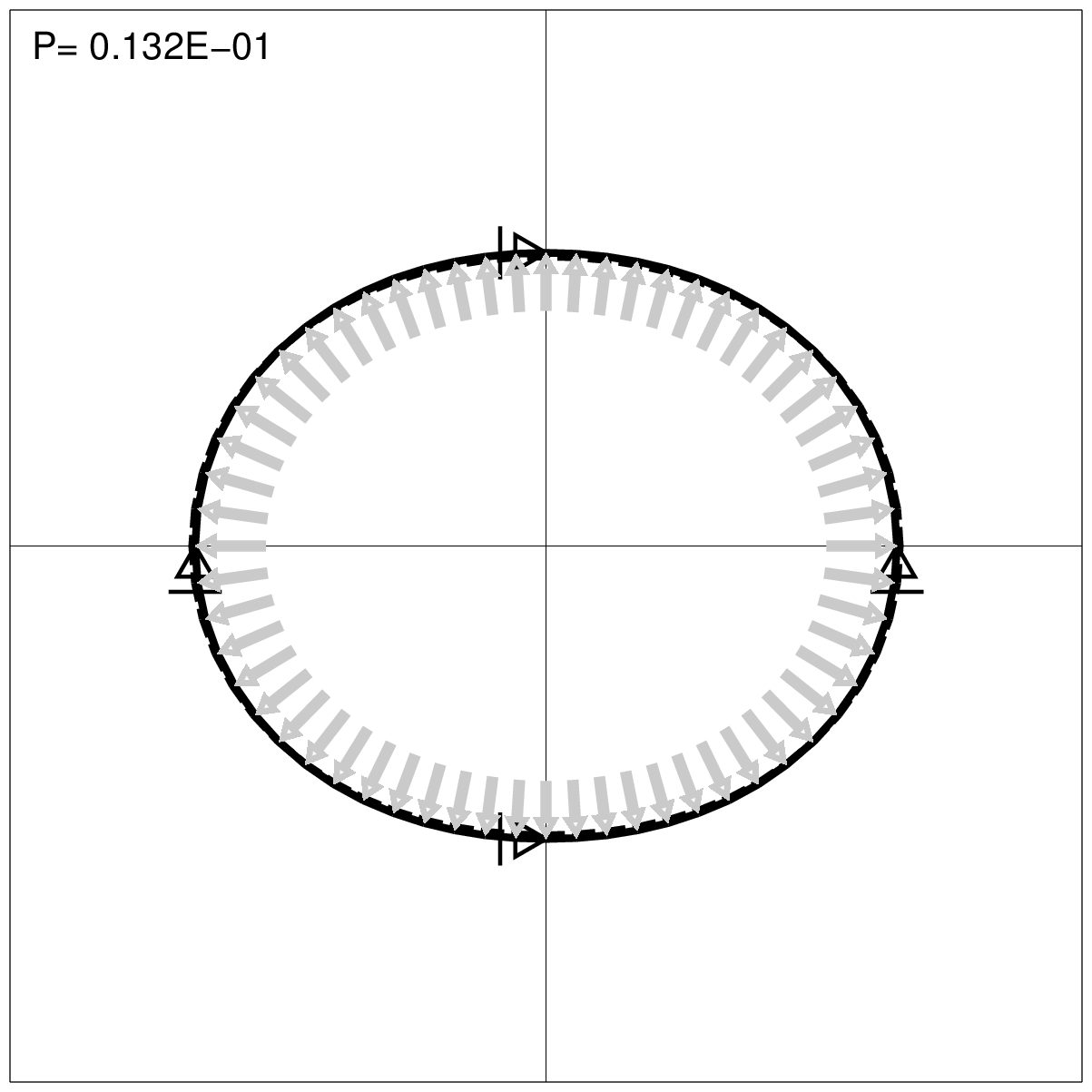
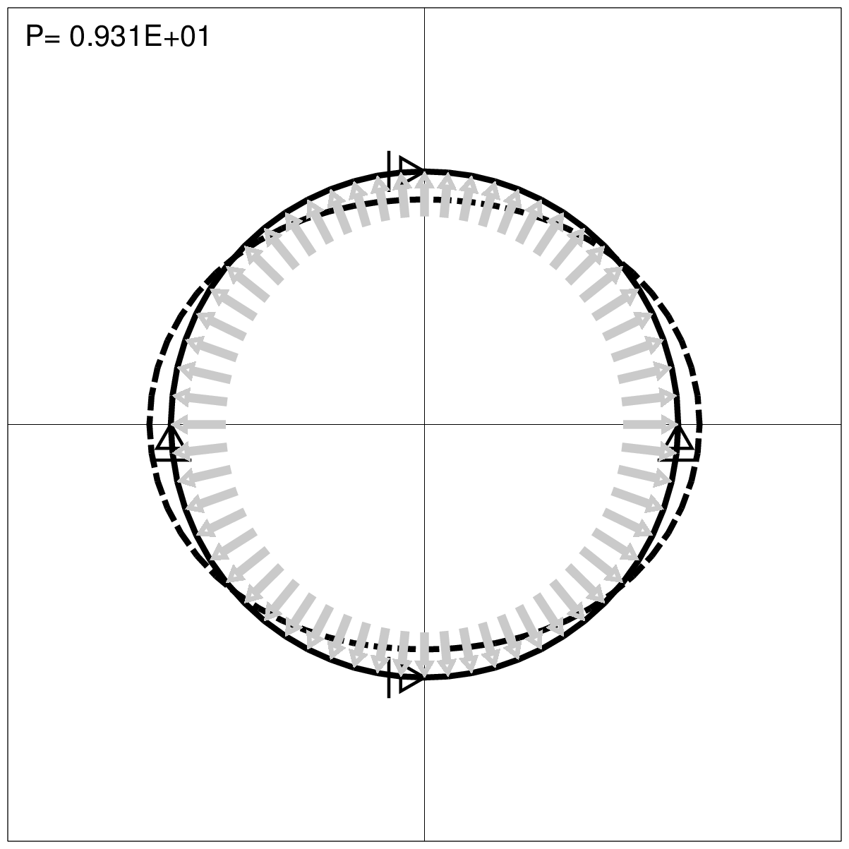
Ring with the large initial deflection under the internal water pressure
| R=1,500 mm | r = 1500 + 150 x cos(2$\theta$) |
| E=200,000 N/mm$^2$ | x = r x cos$\theta$ |
| A=20 mm$^2$ | y = r x sin$\theta$ |
| I=666.6 mm$^4$ | |
| Initial deflection 150 mm |
 | |
 |
 |
Programs and sample data
Fortran programs
| Filename | Description |
|---|---|
| f90_fem_gfrmwp.f90 | f90_fem_gfrmwp.f90 |
| f90_fig_gfrmwp.f90 | f90_fig_gfrmwp.f90 |
| f90_fig_mode.f90 | f90_fig_mode.f90 |
Shell scripts
| Filename | Description |
|---|---|
| a_ctl.txt | a_ctl.txt |
| a_fem.txt | a_fem.txt |
| a_fig.txt | a_fig.txt |
| a_gmt_fig_circ060in.txt | a_gmt_fig_circ060in.txt |
| a_gmt_fig_circ060ot.txt | a_gmt_fig_circ060ot.txt |
| a_mode.txt | a_mode.txt |
Input data samples
| Filename | Description |
|---|---|
| inp_circ060in.csv | inp_circ060in.csv |
| inp_circ060ot.csv | inp_circ060ot.csv |