Outline of a program 'f90_fem_frame.f90'
- This is a program for 2D-Frame Analysis. Elastic and small displacement problems can be treated.
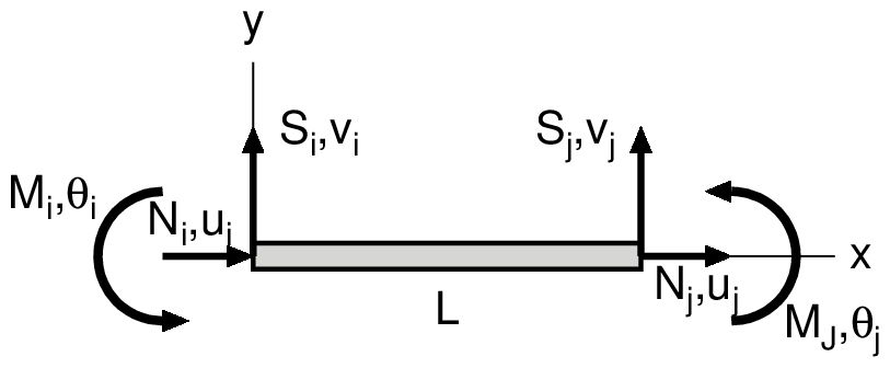
- Beam element with 2 nodes is used. 1 node has 3 degrees of freedom in horizontal, vertical direction and rotation.
- Nodal forces, nodal displacements, nodal temperature changes and inertia forces for element cam be given as loads.
- In coordinate system, x-direction is defined as right-direction, y-direction is defined as upward direction and counterclockwise direction is defined as positive in rotation.
- Simultaneous linear equations are solved using Cholesky method for banded matrix.
- Input/Output file name can be defined arbitrarily with the format of 'csv' and those are inputted from command line of a terminal.
- Used language for program is 'Fortran 90' and used compiler is 'GNU gfortran.'
| Workable condition | |
|---|---|
| Item | Description |
| Element | 2D beam element |
| Load | Specify the loaded nodes and load values |
| Temperature | Specify the temperature changes for all nodes |
| Inertia force | Specify the inertia forces as a ratio to gravity acceleration in horizontal and vertical directions for all elements |
| Displacement | Specify the nodes and displacements at the nodes. Any values can be applied including zero |
| No-tension | Specify the tensile strength of each element. If axial stress exceeds the tensile strength of the element, axial rigidity and bending rigidity will be set approxmately to zero |
The Stiffness matrix of an element is shown below:
\begin{equation*}
\begin{Bmatrix} N_i \\ S_i \\ M_i \\ N_j \\ S_j \\ M_j \end{Bmatrix}
=\begin{bmatrix}
EA/L & 0 & 0 & -EA/L & 0 & 0 \\
0 & 12 EI/L^3 & 6 EI/L^2 & 0 & -12 EI/L^3 & 6 EI/L^2 \\
0 & 6 EI/L^2 & 4 EI/L & 0 & -6 EI/L^2 & 2 EI/L \\
-EA/L & 0 & 0 & EA/L & 0 & 0 \\
0 & -12 EI/L^3 & -6 EI/L^2 & 0 & 12 EI/L^3 & -6 EI/L^2 \\
0 & 6 EI/L^2 & 2 EI/L & 0 & -6 EI/L^2 & 4 EI/L
\end{bmatrix}
\begin{Bmatrix} u_i \\ v_i \\ \theta_i \\ u_j \\ v_j \\ \theta_j \end{Bmatrix}
\end{equation*}
| $EA$ | Axial rigidity | $N$ | Axial forcr | $u$ | Axial displacement (in x-direction) | ||
| $EI$ | Bending rigidity | $S$ | Shearing force | $v$ | Deflection (in y-direction) | ||
| $L$ | Length of element | $M$ | Bending moment | $\theta$ | Rotation |
 |
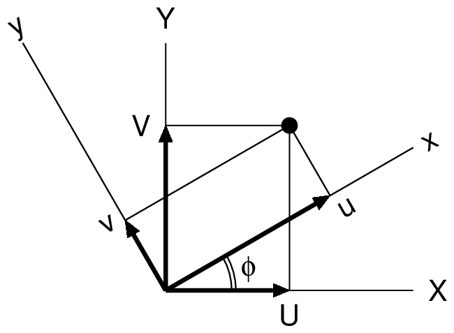 |
| Degrees of freedom of an element | Local coordinate system x-y and Global coordinate system X-Y |
|---|
Transformation matrix from Global coordinate system to Local coordinate system is shown below:
\begin{equation} \begin{Bmatrix} u_i \\ v_i \\ \theta_i \\ u_j \\ v_j \\ \theta_j \end{Bmatrix} = \begin{bmatrix} \cos\phi & \sin\phi & 0 & 0 & 0 & 0 \\ -\sin\phi & \cos\phi & 0 & 0 & 0 & 0 \\ 0 & 0 & 1 & 0 & 0 & 0 \\ 0 & 0 & 0 & \cos\phi & \sin\phi & 0 \\ 0 & 0 & 0 & -\sin\phi & \cos\phi & 0 \\ 0 & 0 & 0 & 0 & 0 & 1 \end{bmatrix} \begin{Bmatrix} U_i \\ V_i \\ \Theta_i \\ U_j \\ V_j \\ \Theta_j \end{Bmatrix} \end{equation}Format of input data file ('csv' format)
Comment                         # Comments
NODT,NELT,MATEL,KOX,KOY,KOZ,NF  # Basic values for analysis
Em,AA,AI,gamma,gkh,gkv,alpha,ts # material properties
    ....(1 to MATEL)....        #
node-1,node-2,matno             # Element connectivity, material set number
    ....(1 to NELT)....         #
x,y,deltaT                      # Node coordinates, temperature change of node
    ....(1 to NODT)....         #
nokx,rdisx                      # Restricted node number and displacement in x-direction
    ....(1 to KOX)....          # (Omit data input if KOX=0)
noky,rdisy                      # Restricted node number and displacement in y-direction
    ....(1 to KOY)....          # (Omit data input if KOY=0)
nokz,rdisz                      # Restricted node number and displacement in rotation
    ....(1 to KOZ)....          # (Omit data input if KOZ=0)
node,fx,fy,fz                   # loaded node number, Load value in x & y-direction, Moment value
    ....(1 to NF)....           # (Omit data input if NF=0)
| NODT | : Number of nodes | Em | : Elastic modulus of element |
| NELT | : Number of elements | AA | : Section area of element |
| MATEL | : Number of material sets | AI | : Moment of inertia of element |
| KOX | : Number of restricted nodes in x-direction | gamma | : Unit weight of element |
| KOY | : Number of restricted nodes in y-direction | gkh | : Horizontal acceleration (ratio to 'g') |
| KOZ | : Number of restricted nodes in rotation | gkv | : vertical acceleration (ratio to 'g') |
| NF | : Number of loaded nodes | alpha | : Coefficient of thermal expansion of element |
| matno | : Material set number | ts | : Tensile strength of element |
Notice
- To input a tensile strength for each material is required. If axial stress exceeds tensile strength of the element, the elastic modulus of the element is set to nearly equal to zero.
- Horizontal and vertical acceleration are defined as the ratio of acted acceleration to gravity acceleration.
- Temperature changes are inputted as them of nodes and they must be written in the same row written the node coordinates. For this item, temperature rising is positive.
- Restricted node means the node which has known (given) displacement. As a known (given) value of nodal displacement, any value can be given including zero for a restricted node.
- Since stress resultants of element are defined as equivalent nodal forces in local coordinate system, it is necessary to note that signs are different from it on general structural mechanics. Positive directions are always right-direction, upward-direction and counterclockwise direction for each node in local coordinate system.
Format of output file ('csv' format)
Comment
NODT,NELT,MATEL,KOX,KOY,KOZ,NF
(Each value for above item)
*node characteristics
node,x,y,fx,fy,fz,fix-x,fix-y,fix-z,rdis-x,rdis-y,rdis-z,deltaT
    node     : Node number
    x,y      : x & y-coordinates
    fx,fy,fz : Nodal forces in x & y direction and Moment of node
    fix-x    : x-direction restricted condition (1: restricted, 0: not restricted)
    fix-y    : y-direction restricted condition (1: restricted, 0: not restricted)
    fix-z    : Restricted condition for rotation (1: restricted, 0: not restricted)
    rdis-x,rdis-y,rdis-z : Displacements in x & y & rotation direction
    deltaT   : temperature change of node
  .....(1 to NODT).....
*element characteristics
element,node-1,node-2,E,A,I,gamma,kh,kv,alpha,ts,matno
    element       : Element number
    node-1,node-2 : Element-nodes relationship
    E             : Elastic modulus of element
    A             : Section area of element
    I             : Moment of inertia of element
    gamma         : Unit weight of element
    kh            : Horizontal acceleration of element (ratio to 'g')
    kv            : Vertical acceleration of element (ration to 'g')
    alpha         : Coefficient of thermal expansion of element
    ts            : Tensile strength of element
    matno         : Material set number
  .....(1 to NELT).....
*displacement and forces
node,x-cood,y-cood,dis-x,dis-y,dis-z,reac-x,reac-y,reac-z,ftvec-x,ftvec-y,ftvec-z
    node                    : Node number
    x-cood,y-cood           : Coordinates in x & y-directions
    dis-x,dis-y,dis-z       : Nodal displacements in x & y & rotation directions
    reac-x,reac-y,reac-z    : Internal forces in x & y & rotation directions
    ftvec-x,ftvec-y,ftvec-z : External forces in x & y & rotation directions
  .....(1 to NODT).....
stress resultants
element,Ni,Si,Mi,Nj,Sj,Mj,noten
    element : Element number
    Ni,Nj   : Axial forces at node 'i' and 'j'
    Si,Sj   : Shear forces at node 'i' and 'j'
    Mi,Mj   : Moments at node 'i' and 'j'
    noten   : Index for no-tension member (0: elastic, 1: no-tension)
  .....(1 to NELT).....
NODT=(Number of node), nt=(nt), mm=(mm), ib=(ib), nnn=(nnn)
Calculation time=(calculation time)
Date_time=(date of execution)
    nt  : Total degrees of freedom of FE equation
    mm  : Dimension of reduced FE equation
    ib  : band width of reduced FE equation
    nnn : Iteration number
Sample calculation and Drawings
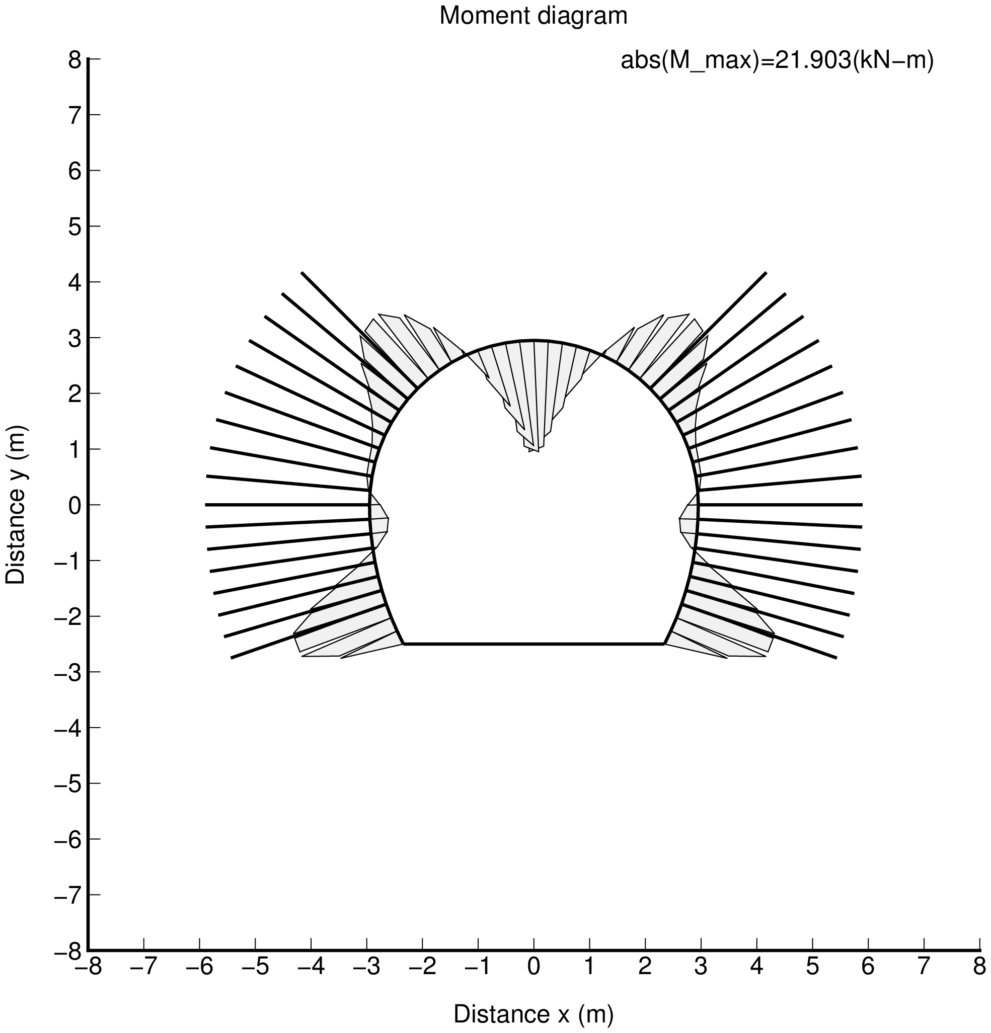
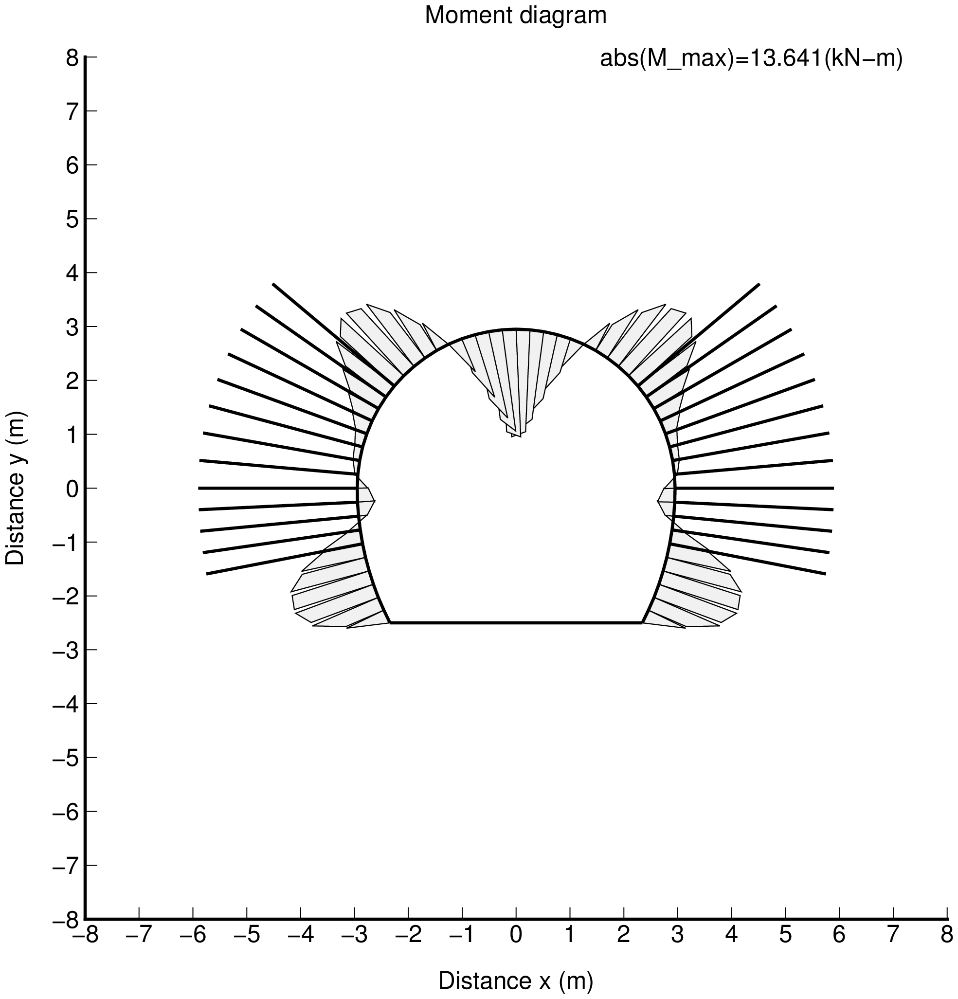
The sample of frame analysis for Shotcrete support of NATM tunnel is shown below. Ground reaction against the deformation of shotcrete member is considered. However, ground reaction acts to the shotcrete members when the stress of ground reaction member is compression only. Therefore, the no-tension characteristics are given to ground reaction elements.
Inputed characteristics
| Item | Value |
|---|---|
| Elastic modulus of the shotcrete wall | 11850 MPa |
| Thickness of the shotcrete wall | 100 mm |
| Elastic modulus of the ground reaction element | 100 MPa (no-tension material) |
| Elastic modulus of the Invert element | 100 MPa (no-tension material, t=400 mm) |
| Vertical load | 0.2 MPa |
| Lateral soil pressure ratio $\lambda$ | 0.0, 0.5, 1.0 |
Drawings
All nodes and elements are shown below. The circumferential elements except the invert are the tunnel support elements, and the radial elements and the invert element are the ground reaction elements.
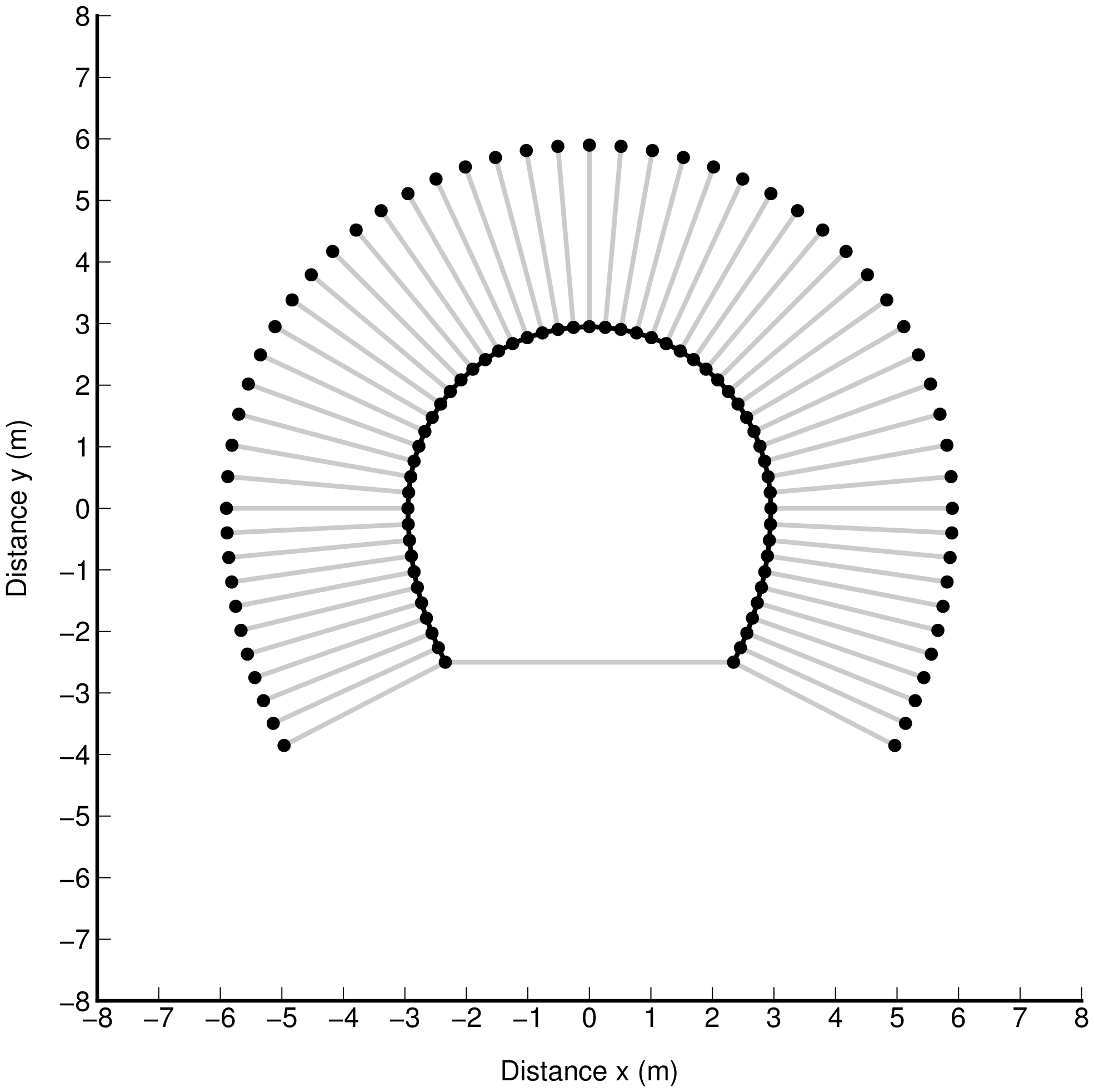 |
| fig_mes.png |
|---|
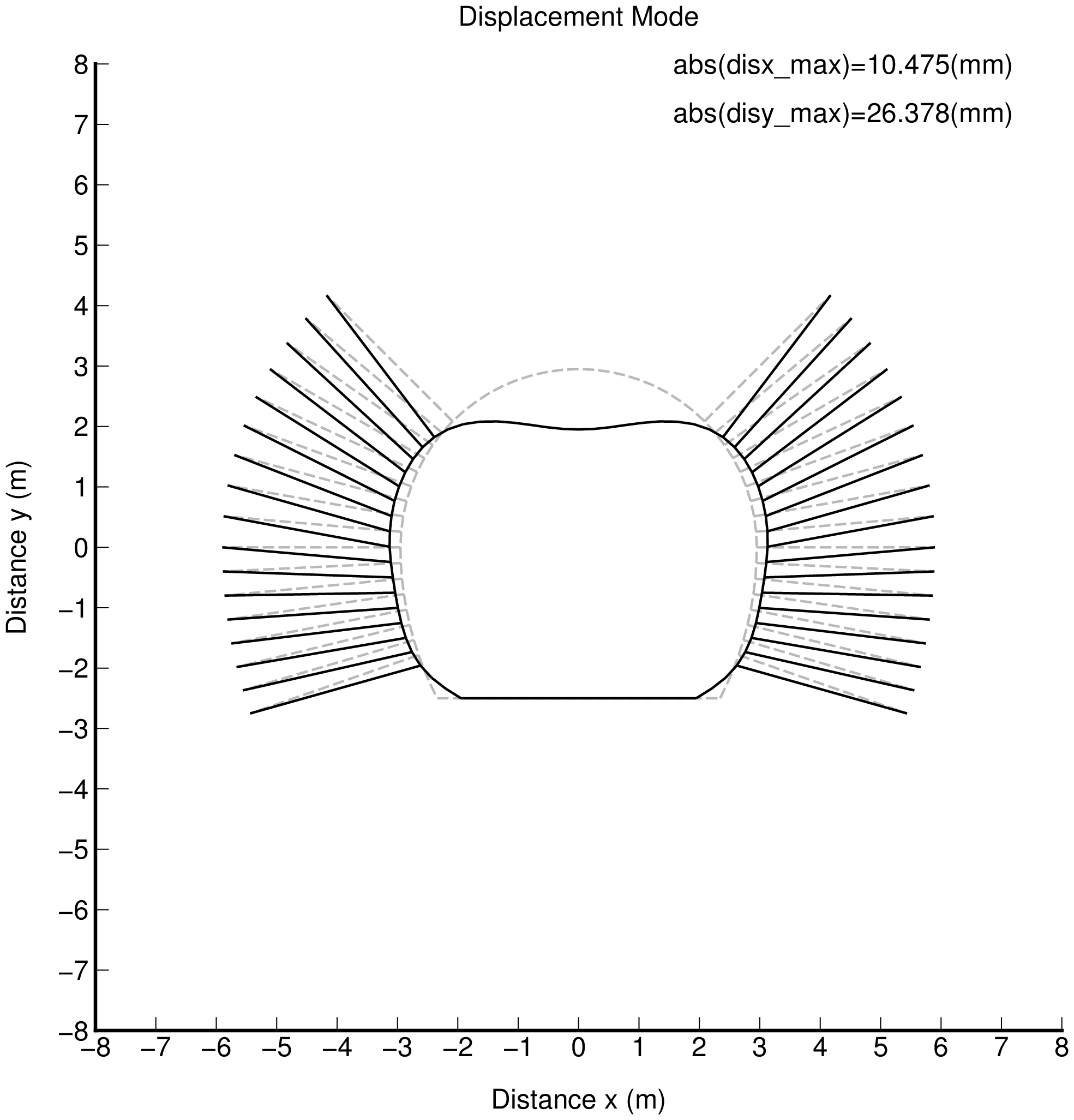
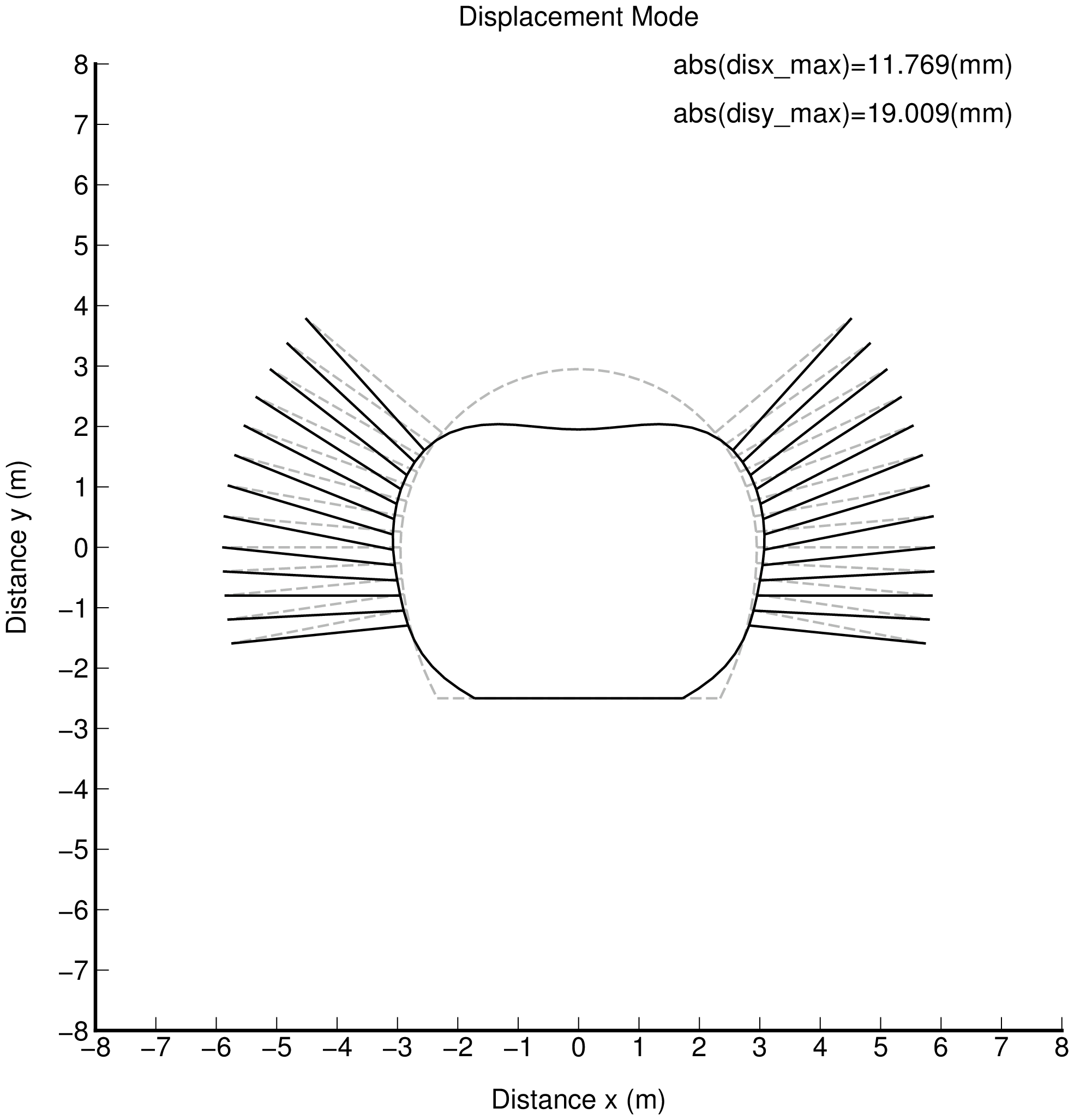
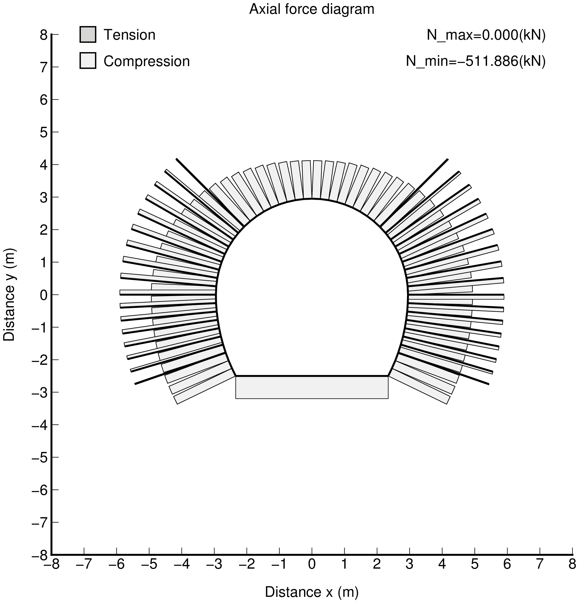
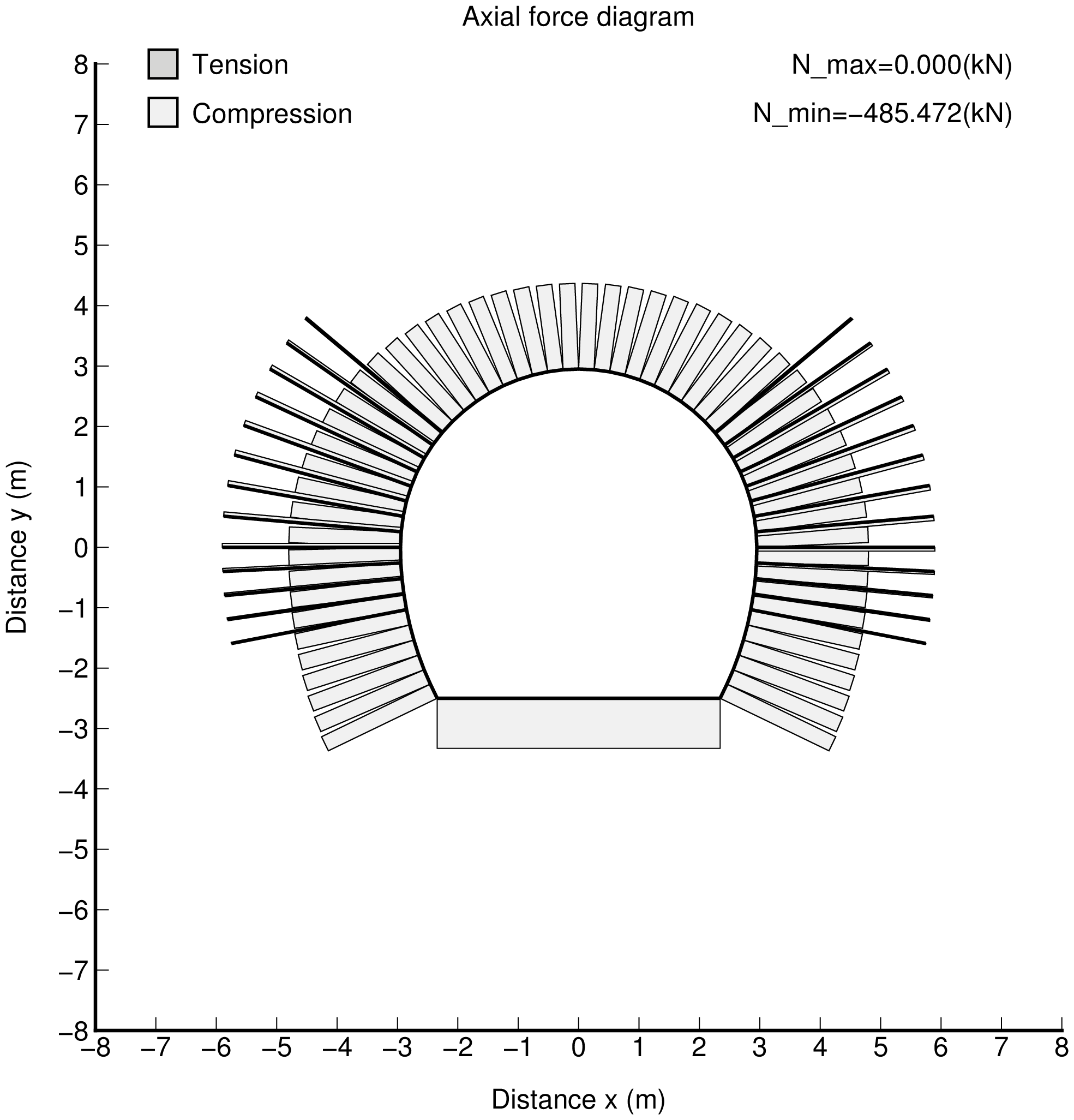
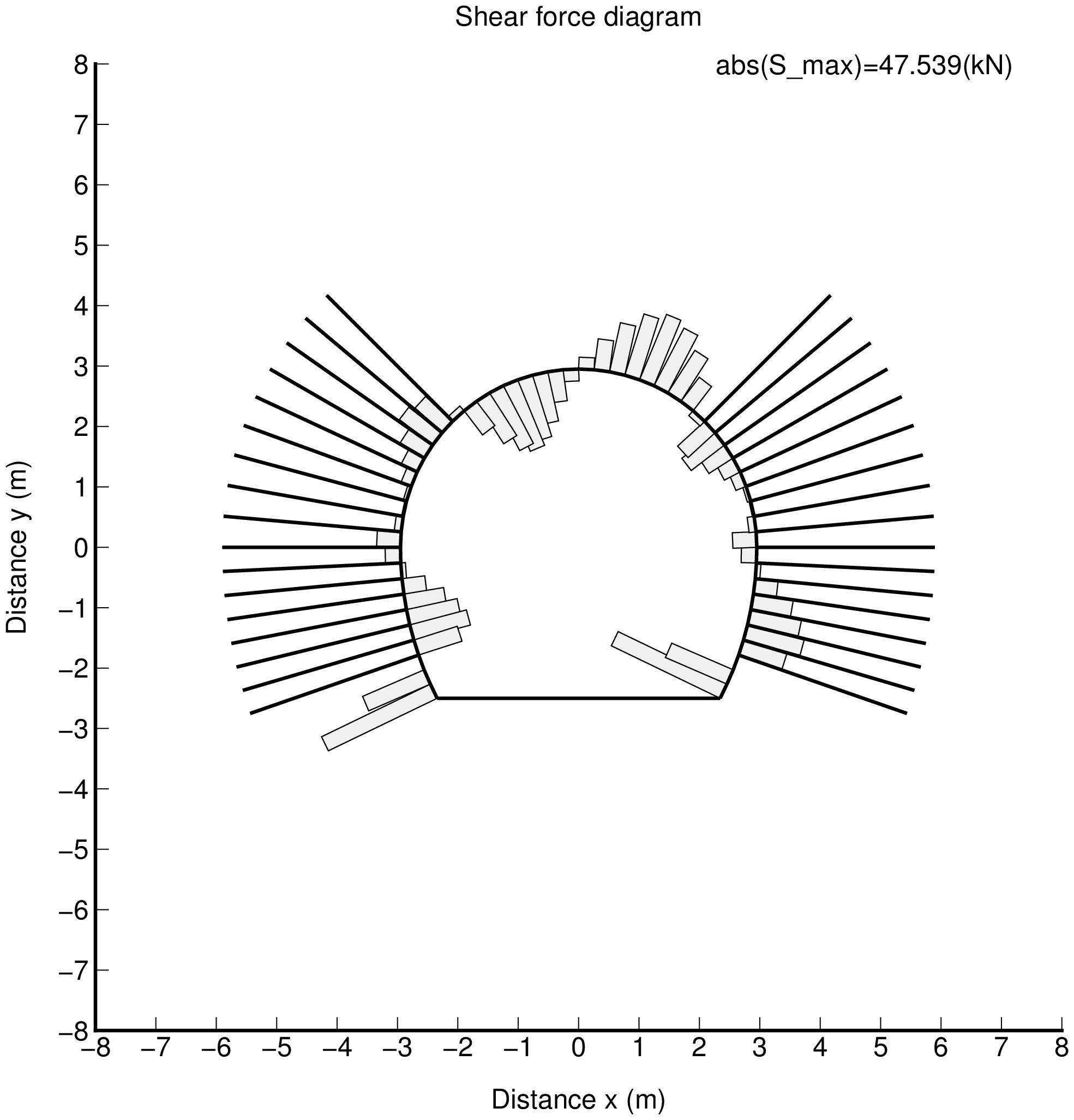
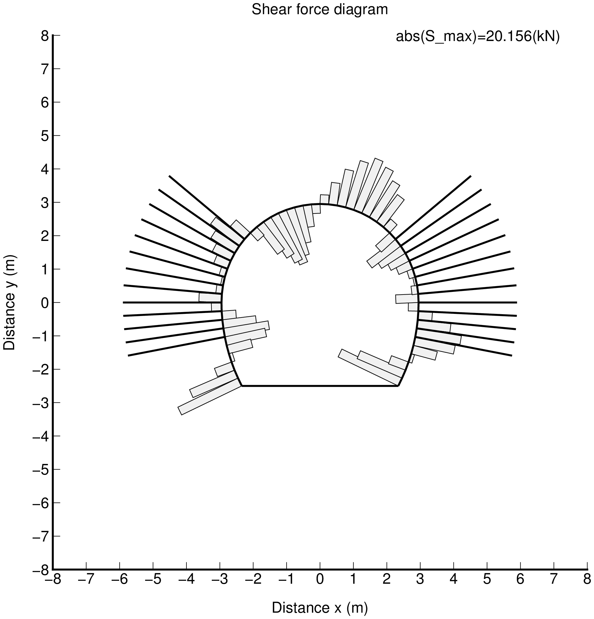
Displacement modes and Stress resultant diagrams are shown below. In those, no-tension elenemts are deleted.
| $\lambda=0.0$ | $\lambda=0.5$ | $\lambda=1.0$ |
|---|---|---|
 |
 |
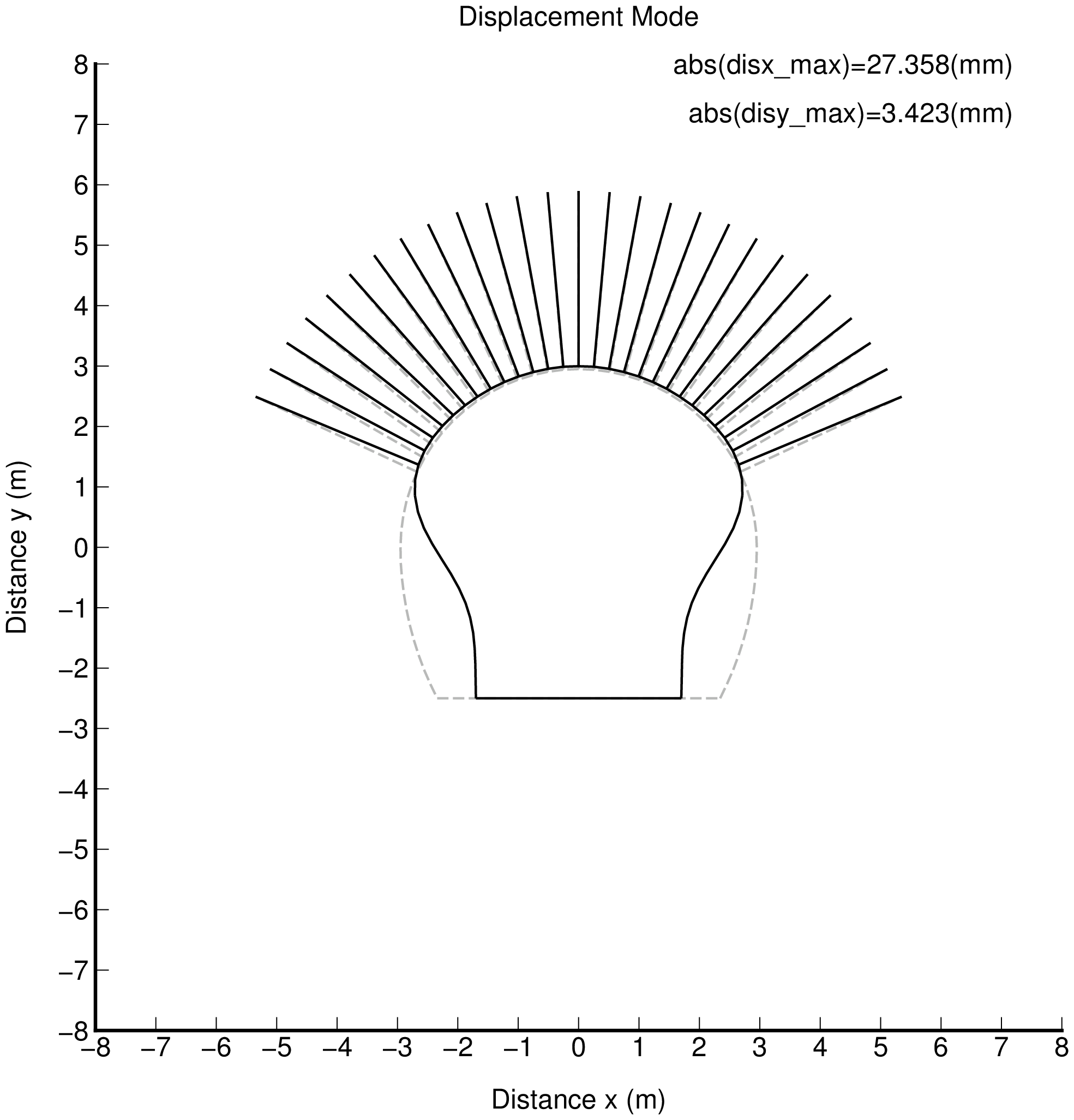 |
| fig_dis_1.png | fig_dis_2.png | fig_dis_3.png |
 |
 |
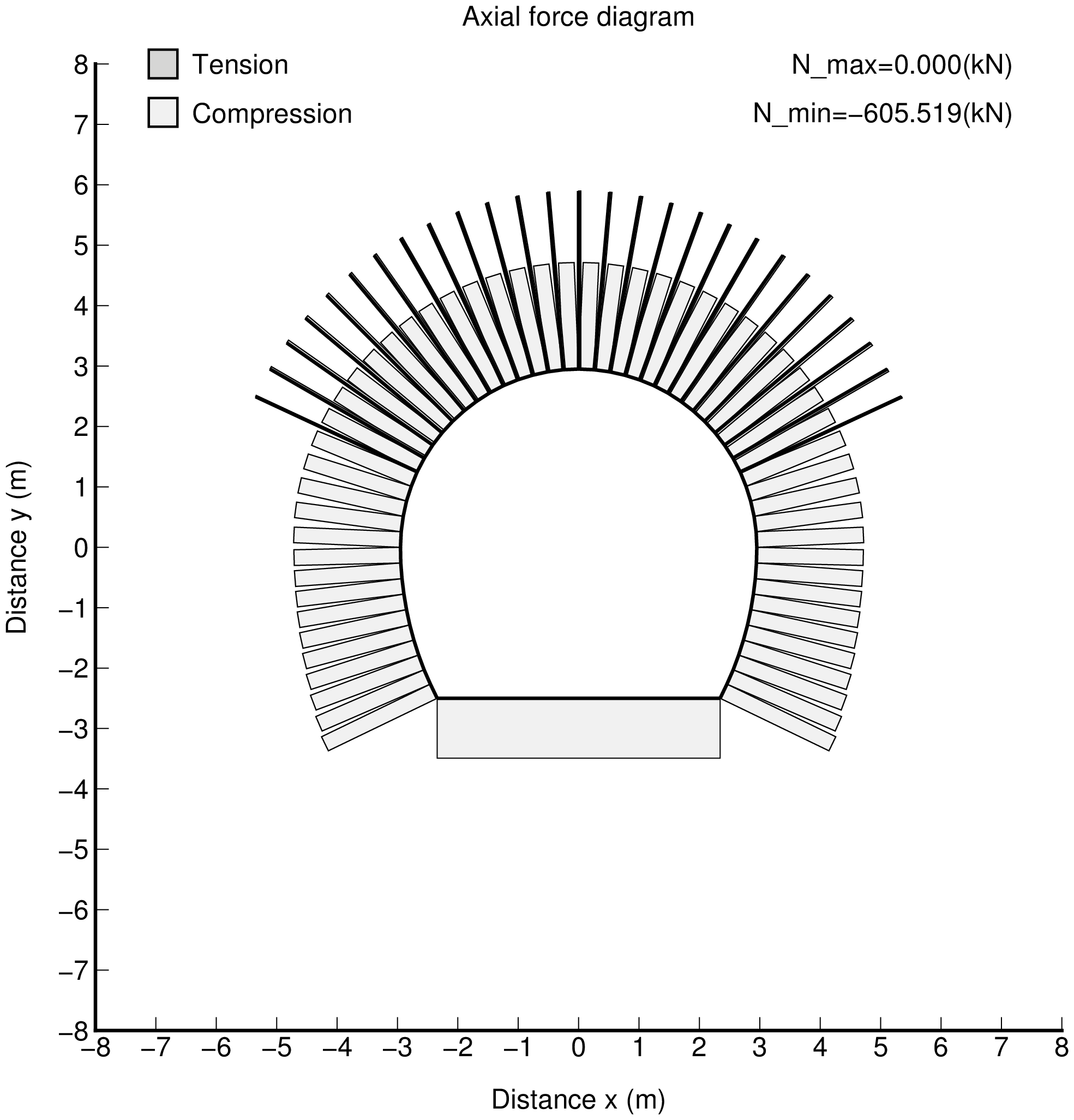 |
| fig_axi_1.png | fig_axi_2.png | fig_axi_3.png |
 |
 |
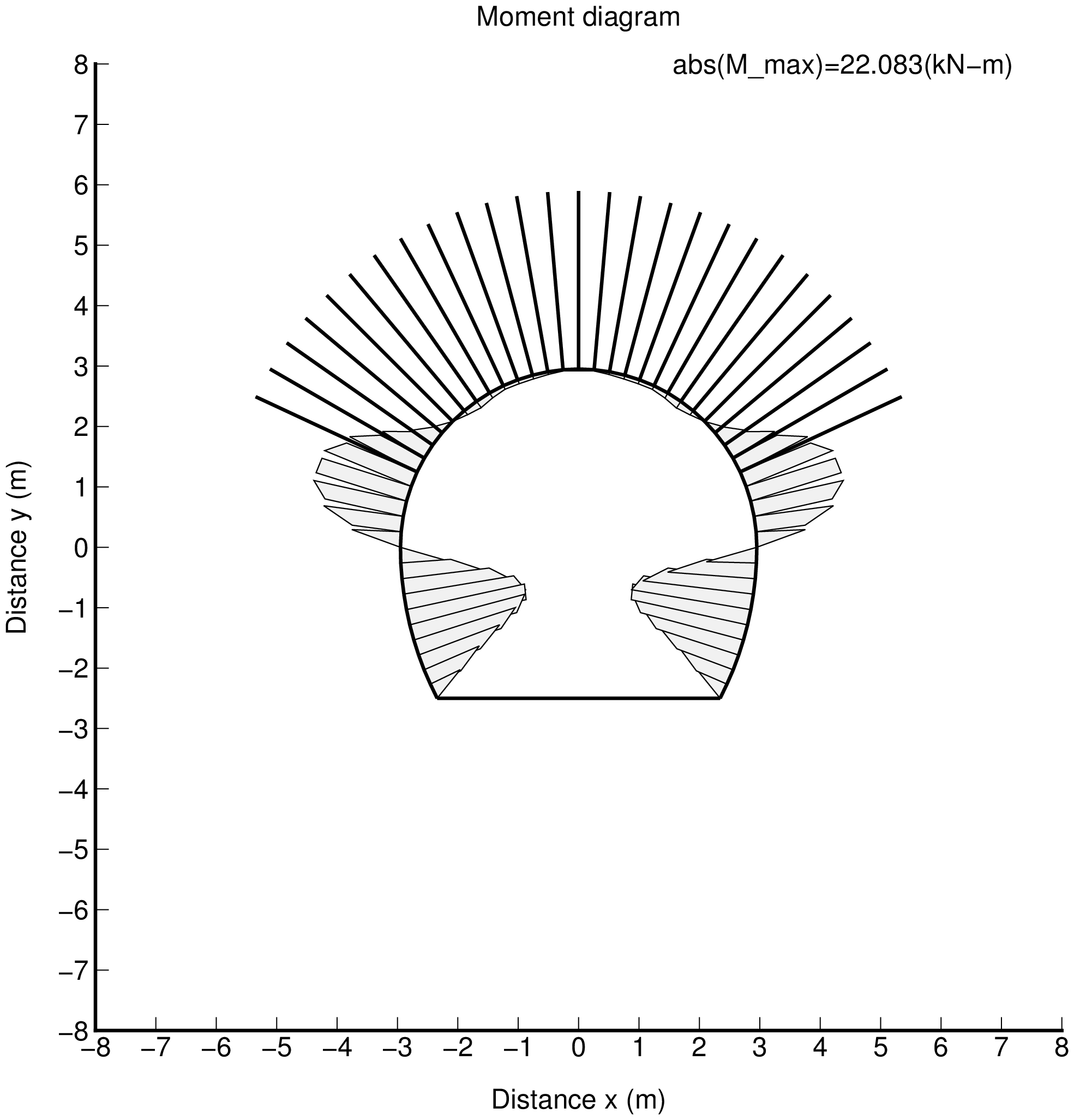 |
| fig_mom_1.png | fig_mom_2.png | fig_mom_3.png |
 |
 |
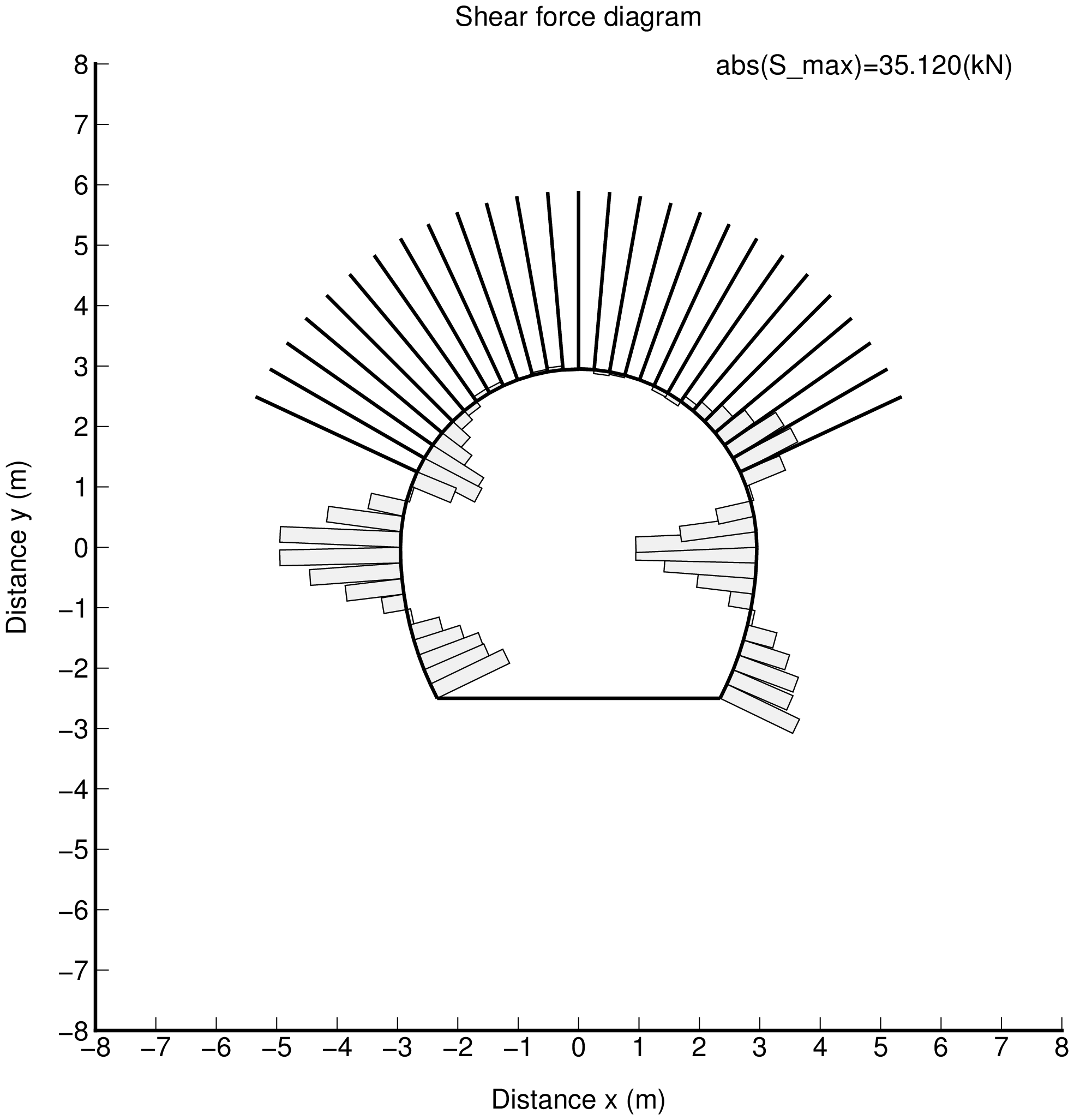 |
| fig_she_1.png | fig_she_2.png | fig_she_3.png |
Programs and Data samples
Programs
| Filename | Description |
|---|---|
| f90_fem_frame.f90 | Frame analysis |
| a_f90.txt | Shell script for control |
| a_gmt_frame_resul.txt | Shell script for GMT drawings |
| py_frame_data1.py | Python3 program for making input data |
| py_frame_resul.py | Python3 program for making drawing data |
| a_gmt_model.txt | Drawings of coordinate system, etc |
Data samples
| Filename | Description |
|---|---|
| inp_div_frm1.csv | Input data sample (1) |
| inp_div_frm2.csv | Input data sample (2) |
| inp_div_frm3.csv | Input data sample (3) |