Formula by the standard in Japan
In 'Technical Standards for Gates and Penstocks' in japan, the critical buckling pressure is prescribed as follow. It is based on the paper by Amstutz in 1953. (AMSTUTZ,E. "Das Einbeulen von vorgespannten Schacht-und Stollenpanzerungen", Schweizerische Bauzeitung,71,1953,N.16,p229. by Amstutz in 1953.)
(1) Equation for defining the axial stress at the moment of buckling ( $\sigma_N$ )
\begin{equation}
\left(\frac{k_0}{r_m}+\frac{\sigma_N}{E_s^*}\right)\left(1+12\frac{{r_m}^2}{t^2}\frac{\sigma_N}{E_s^*}\right)^{1.5}
=3.36\frac{r_m}{t}\frac{\sigma_F^*-\sigma_N}{E_s^*}\left(1-\frac{1}{2}\frac{r_m}{t}\frac{\sigma_F^*-\sigma_N}{E_s^*}\right) \qquad\qquad (1)
\end{equation}
(2) Critical buckling pressure
\begin{equation}
p_k=\cfrac{\sigma_N}{\cfrac{r_m}{t}\left(1+0.35\cfrac{r_m}{t}\cfrac{\sigma_F^*-\sigma_N}{E_s^*}\right)} \qquad\qquad (2)
\end{equation}
(3) Properties of steel material
\begin{equation}
E_s^*=\frac{E_s}{1-{\nu_s}^2} \qquad
\sigma_F^*=\mu\frac{\sigma_F}{\sqrt{1-\nu_s+{\nu_s}^2}} \qquad
\mu=1.5-0.5\cfrac{1}{(1+0.002\cdot E_s/\sigma_F)^2}
\end{equation}
(4) Gap between outer surface of steel pipe and inner surface of backfill concrete
\begin{equation}
k_0=\cfrac{(\alpha_s\Delta T+\beta_g\sigma_a\eta/E_s) r_0'}{1+\beta_g}
\end{equation}
If compressive stress $\sigma_v$ is applied in the steel pipe, $k_0/r_m$ shall be changed to $-\sigma_v/E_s^*$ .
(5) Definitions of symbols
| $p_k$ | : Critical buckling pressure |
| $D_0$ | : Internal diameter of the pipe |
| $t_0$ | : Plate thickness of the pipe |
| $t$ | : plate thickness of the pipe excluding margin thickness ($=t_0-\epsilon$) |
| $\epsilon$ | : Margin thickness for corrosion and wear |
| $E_s$ | : Elastic modulus of steel |
| $\nu_s$ | : Poison's ratio of steel |
| $r_m$ | : Radius to the center of shell thickness ($=(D_0+t_0)/2$) |
| $r_0'$ | : Radius to the external surface of shell ($=(D_0+2 t_0)/2$) |
| $\sigma_N$ | : Critical axial stress at the moment of buckling |
| $\sigma_F$ | : Yield stress of steel shell |
| $E_s^*$ | : Modified elastic modulus including Poisson's effect |
| $\sigma_F^*$ | : Modified yield stress including Poisson's effect |
| $\mu$ | : Coefficient for supporting effect |
| $k_0$ | : Gap between concrete and external surface of steel pipe |
| $\alpha_s$ | : Coefficient of thermal expansion of steel |
| $\Delta T$ | : Temperature change of steel pipe (positive is decrease of temperature) |
| $\beta_g$ | : Plastic deformation modulus of be |
| $\eta$ | : Joint efficiency |
| $\sigma_a$ | : Allowable stress of steel pipe |
Formula by Amstutz (1970)
According to the paper by Ernst Amstutz ''Buckling of pressure-shaft and tunnel linings: Water Power November 1970'', the critical buckling pressure of embedded steel pipe is defined as follow.
In this paper, not only the cases of perfect circular pipe but also the case of the pipe with imperfections such as initial deflection and offset of the joint are described.
Basic formula for perfect circular pipe
Following assumptions are introduced as the basis of the analysis in order to derive the critical buckling pressure of embedded steel pipe.
Assumption by Amstutz
- Displacement of steel pipe in outer direction is restricted by the backfilled concrete.
- Steel pipe has completely elastic body and backfilled concrete is considered as a rigid body.
- Deflection mode of steel pipe is approximated as trigonometrical function.
- Reduction of restriction by the gap between concrete and external surface of the steel pipe, or Increase of restriction by the pre-stress is considered.
- The compressive stress of external surface (uniform compression + bending stress) of the pipe is equal to the yield stress of steel pipe at the moment of buckling.
- Since steel pipe considered is embedded in rock zone, restriction by Poisson's effect is considered for elastic modulus and yield stress of the steel pipe. ( $E_s$ is increased to $E_s^*$ using Poisson's ration $\nu_s$ .)
- Since ultimate bending strength of the steel is greater than initial yield bending strength, critical strength of the pipe is increased using coefficient of supporting effect. ( $\sigma_F$ is increased to $\sigma_F^*$ using Poisson's ratio $\nu_s$ and coefficient for supporting effect $\mu$ .)
Formulas for calculation of critical buckling strength
(1) Equation for defining the axial stress at the moment of buckling ( $\sigma_N$ )
\begin{equation}
\left(\frac{k_0}{r_m}+\frac{\sigma_N}{E_s^*}\right)\left(1+12\frac{{r_m}^2}{t^2}\frac{\sigma_N}{E_s^*}\right)^{1.5}=2\Phi\frac{r_m}{t}\frac{\sigma_F^*-\sigma_N}{E_s^*}\left(1-2\Psi\frac{r_m}{t}\frac{\sigma_F^*-\sigma_N}{E_s^*}\right) \qquad\qquad (3)
\end{equation}
(2) Critical buckling pressure
\begin{equation}
p_k=\cfrac{\sigma_N}{\cfrac{r_m}{t}\left(1+2\Omega\cfrac{r_m}{t}\cfrac{\sigma_F^*-\sigma_N}{E_s^*}\right)} \qquad\qquad (4)
\end{equation}
(3) Properties of steel material
\begin{equation}
E_s^*=\frac{E_s}{1-{\nu_s}^2} \qquad
\sigma_F^*=\mu\frac{\sigma_F}{\sqrt{1-\nu_s+{\nu_s}^2}} \qquad
\mu=1.5-0.5\cfrac{1}{(1+0.002\cdot E_s/\sigma_F)^2}
\end{equation}
(4) Definition of each coefficient
\begin{align}
&\Phi=\frac{\epsilon^3\beta}{\pi\delta} \qquad \Psi=-\frac{\gamma}{4\beta\delta} \qquad \Omega=-\frac{\cos(\epsilon\alpha)}{1-\cos(\epsilon\alpha)} \\
&\epsilon=\sqrt{1+12\left(\frac{r_m}{t}\right)^2\frac{\sigma_N}{E_s^*}} \\
&\beta=\left(\epsilon-\frac{1}{\epsilon}\right)[\epsilon\alpha\cos(\epsilon\alpha)-\sin(\epsilon\alpha)] \\
&\gamma=-\epsilon\left[\epsilon\alpha-\sin(\epsilon\alpha)\cos(\epsilon\alpha)+\epsilon\alpha\frac{\sin^2(\epsilon\alpha)}{\sin^2(\alpha)}-\epsilon\sin^2(\epsilon\alpha)\cot(\alpha)\right] \\
&\delta=(\epsilon^2-1)[1-\cos(\epsilon\alpha)]
\end{align}
(5) Condition of deflection mode
\begin{equation}
\epsilon\tan\alpha=\tan(\epsilon\alpha) \qquad ( 0 < \alpha\leqq\pi/2 )
\end{equation}
where, $\alpha$ means the half angle of deflected range, and unit is degree.
Effect of initial deflection
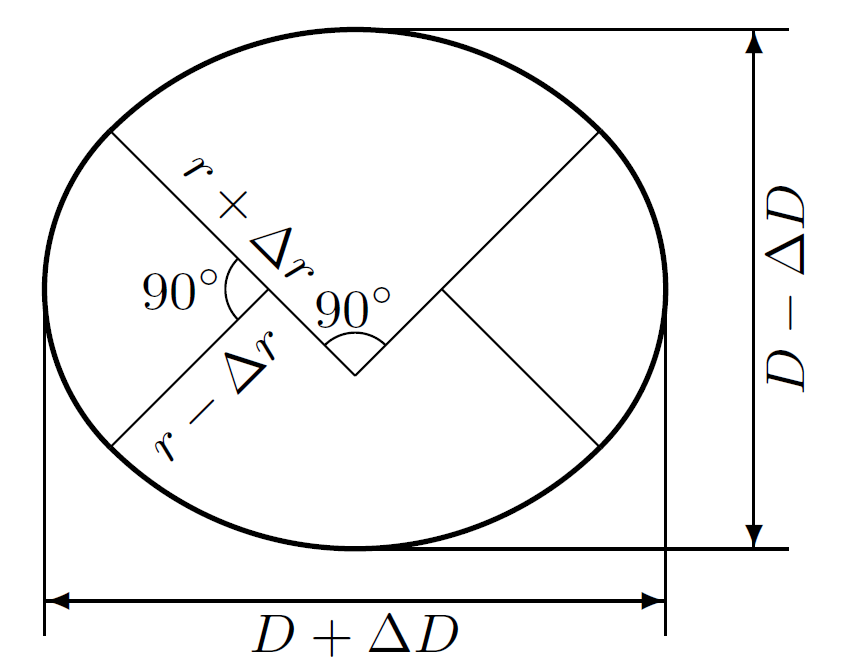
It is considered that imperfect circular section is composed by the parts of four perfect circle. And the idea is adopted that radius for perfect circular pipe $r$ is increased to $r+\Delta r$ taking into consider oblateness of the pipe.
The relationship between the pipe's diameter $D$ and pipe's radius $r$ is shown below.
\begin{equation}
\frac{\Delta r}{r}=\left(\frac{\sqrt{2}/2+1}{3\sqrt{2}/2-1}\right)\cdot\frac{\Delta D}{D} \qquad \qquad
\Delta r=\left(\frac{\sqrt{2}/2+1}{3\sqrt{2}/2-1}\right)\cdot\frac{\Delta D}{D}\cdot r
\end{equation}
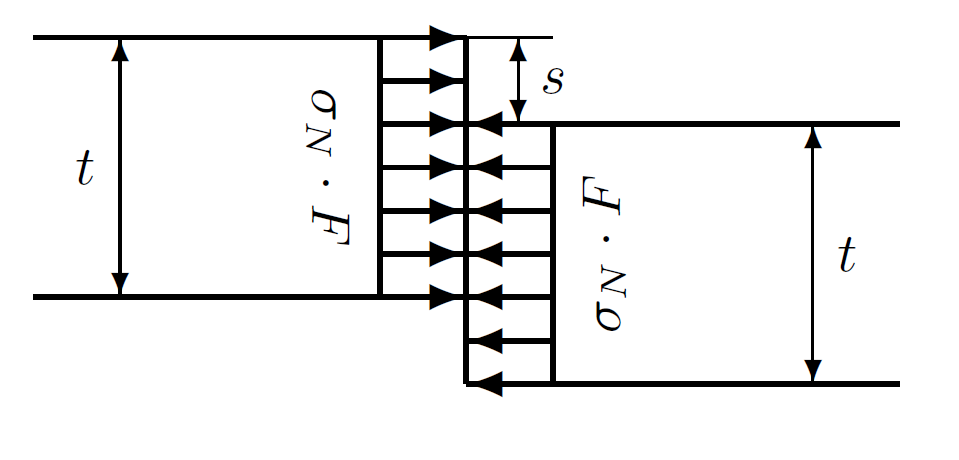
Effect of offset at the welded joint
Additional bending stress due to additional moment caused by offset at the welded joint is considered. And the equations to calculate the critical axial stress $\sigma_N$ and buckling pressure $P_{cr}$ are modified as follow.
Additional moment $\Delta M$ and additional bending stress $\Delta\sigma$ are expressed as follow.
\begin{equation}
\Delta M=F\cdot\frac{s}{2}\cdot\sigma_N \qquad \qquad \Delta\sigma=\pm 3\cdot\frac{s}{t}\cdot\sigma_N
\end{equation}
Then, following equation is adopted for the calculation of $\sigma_N$ and $P_k$ .
\begin{equation}
(\sigma_F-\sigma_N) \rightarrow (\sigma_F-m\cdot\sigma_N) \qquad\qquad m=1+3\cdot\frac{s}{t}
\end{equation}
It means that equation (3) and equation (4) is modified using parameter $m$ .
\begin{equation}
\left(\frac{k_0}{r_m}+\frac{\sigma_N}{E_s^*}\right)\left(1+12\frac{{r_m}^2}{t^2}\frac{\sigma_N}{E_s^*}\right)^{1.5}=2\Phi\frac{r_m}{t}\frac{\sigma_F^*-m\cdot\sigma_N}{E_s^*}\left(1-2\Psi\frac{r_m}{t}\frac{\sigma_F^*-m\cdot\sigma_N}{E_s^*}\right) \qquad\qquad (5)
\end{equation}
\begin{equation}
p_k=\cfrac{\sigma_N}{\cfrac{r_m}{t}\left(1+2\Omega\cfrac{r_m}{t}\cfrac{\sigma_F^*-m\cdot\sigma_N}{E_s^*}\right)} \qquad\qquad (6)
\end{equation}
 |
 |
| Combined section with four parts of perfect circle |
Model of offset at the welded joint |
|---|
Estimation of critical buckling pressure
The values of $\Phi$ , $\Psi$ and $\Omega$ depend on the value of $\sigma_N$ , and they are not constant in Amstutz's formula (1970). However, they are constant values in TSGP (Technical Standards for Gates and Penstocks) in japan as follow.
\begin{equation}
\Phi=1.68 \qquad \Psi=0.25 \qquad \Omega=0.175
\end{equation}
It can be understood comparing equation (1) and (2) with equation (3) and (4). These values were shown in the paper by Amstutz (1953), and these were derived based on geometrical consideration.
The result of comparison of critical buckling pressures using TSGP formula and Amstutz formula (1970) are shown below.
Conditions of estimation
The relationship between the value of the ratio (radius / shell thickness) and critical buckling pressure were estimated using two formulas. In this study, design pipe diameter $D_0$ was varied and design shell thickness of pipe was fixed as the value of $t_0=30mm$ .
Conditions for estimation is shown below.
Conditions for calculation of critical buckling pressure
| General conditions | ||
|---|---|---|
| $t_0=30 mm$ | $D_0/2t_0=35\sim 140$ | $\epsilon=1.5 mm$ |
| $E_s=206,000 MPa$ | $\nu_s=0.3$ | $\alpha_s=1.2\times10^{-5} /^\circ C$ |
| $\eta=1.0$ | $\Delta T=20 ^\circ C$ | $\beta_g=1.0$ |
| Yield point and allowable stress | |||||
|---|---|---|---|---|---|
| Material | HT100 | SHY685 | SM570 | SM490 | SM400 |
| $\sigma_F$ | 885 | 685 | 450 | 315 | 235 |
| $\sigma_a$ | 400 | 330 | 240 | 175 | 130 |
| Initial imperfection | ||
|---|---|---|
| Initial deflection | $D_0$/300 | Assumed |
| Offset at welded joint | 0.05 $t_0$ | Japanese standard |
Result
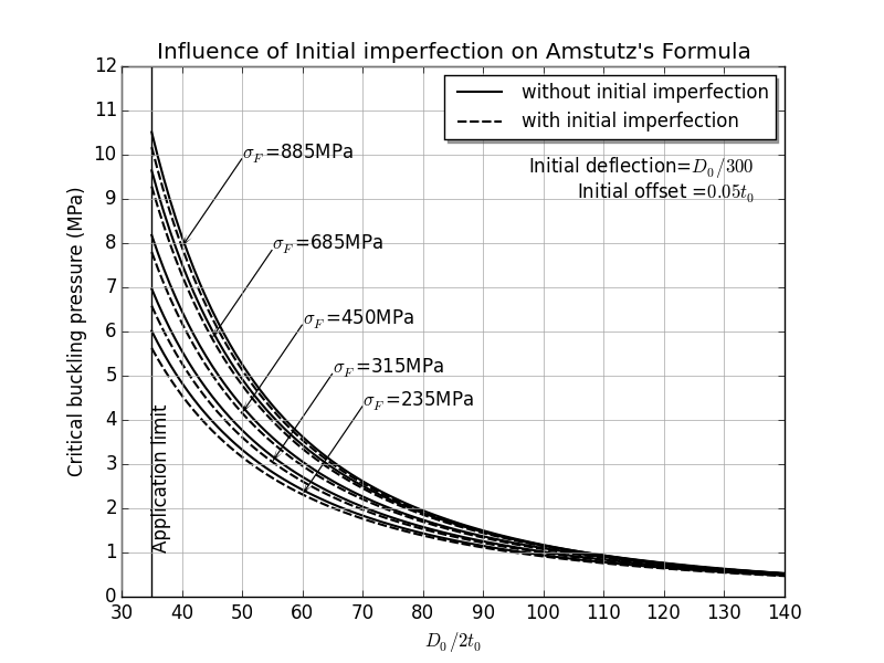
Estimated results are shown in Fig.1 and Fig.2.
In Fig.1, the effect of initial imperfection is indicated using Amstutz's formula (1970). This graph is made using equation (3), (4) and equation (5), (6).
In Fig.2, the difference between Amstutz's formula (1970) with initial imperfections and TSGP formula in japan is shown. This graph is made using equation (1), (2) and equation (5), (6).
In these conditions, initial imperfection does not have large influence to the critical buckling pressure. Moreover, the formula by TSGP in japan gives the result of safety side as compared with the Amstutz's formula (1970) with initial imperfection.
 |
 |
| Fig.1 Influence of initial imperfection by Amstutz's formula |
Fig.2 Conmarison between Japan standard and Amstutz's formula |
|---|
Programs and references
Programs
Programs for Demonstration
| Filename | Description |
|---|---|
| a_ams.txt | Shell script for execution |
| f90_ams_jpn.f90 | Calculation by Japan standard |
| f90_ams_org.f90 | Calculation by Amstutz formula |
| py_plot1.py | Drawing by Python3 (1) |
| py_plot2.py | Drawing by Python3 (2) |
References
- ''Technical Standards for Gates and Penstocks'' in Japan
- Ernst Amstutz: ''Das Einbeulen von vorgespannten Schacht-und Stollenpanzerungen'', Schweizerische Bauzeitung,71,1953,N.16,p229
- Ernst Amstutz: ''Buckling of pressure-shaft and tunnel linings'', Water Power November 1970